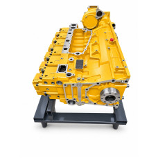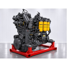

Complete REMAN Komatsu SAA6D140E-5 engine: guide
Complete REMAN Komatsu SAA6D140E-5 engine: what the assembly includes, 15.24 L, specifications, part numbers and applications. How to select the engine for your machine and what to know before ordering.
In brief: what you need to know about the complete REMAN Komatsu SAA6D140E-5 engine
- What it is. A remanufactured (REMAN) complete engine: a Komatsu six-cylinder in-line diesel with a displacement of 15.24 L (140 × 165 mm), turbocharged, with air-to-air charge-air cooling, an electronic Common Rail fuel system (up to 160 MPa) and, on versions without the “R” suffix, cooled EGR. Tier 3 / Stage 3A generation.
- How much power. Output depends on the version for each machine: from 266 kW (357 hp) in the WA500-6 loader and 268 kW in the D155AX-6 dozer up to 386 kW (518 hp) in the HD325-7 / HD405-7 haul trucks. PC800-8 — 370 kW, HM400-2 — 338 kW, D275AX-5E0 — 337 kW, PC600-8 — 323 kW, HM350-2 — 304 kW.
- Where it is fitted. D155AX-6 and D275AX-5E0 dozers, WA500-6 wheel loader, HD325-7 / HD405-7 rigid haul trucks, HM350-2 and HM400-2 / -3 articulated trucks, PC600-8, PC700-8 and PC800 / PC850-8 excavators — 16 groups of versions (EGR versions and “R” versions without EGR).
- What a complete engine is. The entire power unit: the mechanical core (block, crankshaft, pistons, heads), the KTR110L turbocharger, the Common Rail fuel system, the controller and sensors, manifolds, flywheel, oil and coolant circuits, starter motor and alternator; optionally — the front gear cover, oil cooler and water pump. The boundary between “engine” and “machine” and the scope of supply are fixed in the specification before payment.
- Komatsu numbers. In reference catalogues the complete engine appears as RM6261-A0-0020 (WA500-6), RM6261-H0-0033 (D275AX-5E0) and 6261-C0-0060 (HM400-2); the long block is RM6261-LE-0100. There is no single number for the whole family: selection is by version and serial number.
- The main selection rule. Data plate (model with letter and ESN) → machine with suffix (E0, R) → EGR or non-EGR version → variant → ancillaries → options → specification. We run this check against a photo of your data plate before payment.
- What we have. The REMAN Komatsu SAA6D140E-5 complete engine is a remanufactured Komatsu engine supplied by CATKOMPARTS; see the SAA6D140E-5 engine page in our reference, and at long-block level — product page 499. Specification and data plate photo before payment, individual warranty, pickup in Brazil and export, delivery to Russia as far as the customs port by agreement.
How to read this article. If you want to understand what a REMAN engine is and how it differs from a long block — part I (sections 1–4). If you are a buyer selecting an assembly — sections 5–10 and the questions and answers at the end. If you are an engineer or mechanic — part II (design by system, versions, specifications, data sheets by machine) and part III (dimensions, torques, standards, run-in, ECU codes, diagnostics, installation). Part III is reference material and does not have to be read in sequence.
Part I. In plain language: what a complete REMAN engine is
1. What the complete REMAN Komatsu SAA6D140E-5 engine is
Komatsu SAA6D140E-5 is a six-cylinder in-line diesel with a displacement of 15.24 L for heavy Komatsu mining and construction equipment: dozers, wheel loaders, rigid and articulated haul trucks, and heavy PC600–PC850 excavators. The engine is built to run several shifts in a row, where an hour of downtime costs more than the repair itself.
A complete REMAN engine is the whole power unit: cylinder block with liners, crankshaft, pistons with connecting rods, heads with valves, valve train, oil pump and sump, flywheel with housing, damper, turbocharger, Common Rail fuel system with the high-pressure pump, injectors and controller, engine cooling system, starter motor, alternator and engine wiring. Unlike a long block, with this unit you do not have to transfer ancillaries from the old engine: it is removed as a whole and the ready-made unit is installed.
The word REMAN (remanufactured) means that the engine has been disassembled, cleaned, inspected part by part, reassembled with worn components replaced or restored to the dimensions in the Komatsu manual, and tested before shipment. This is a separate product category: not a new engine and not one “repaired on site”. The complete REMAN engine for the SAA6D140E-5 is a Komatsu product that we supply; details are in section 10.
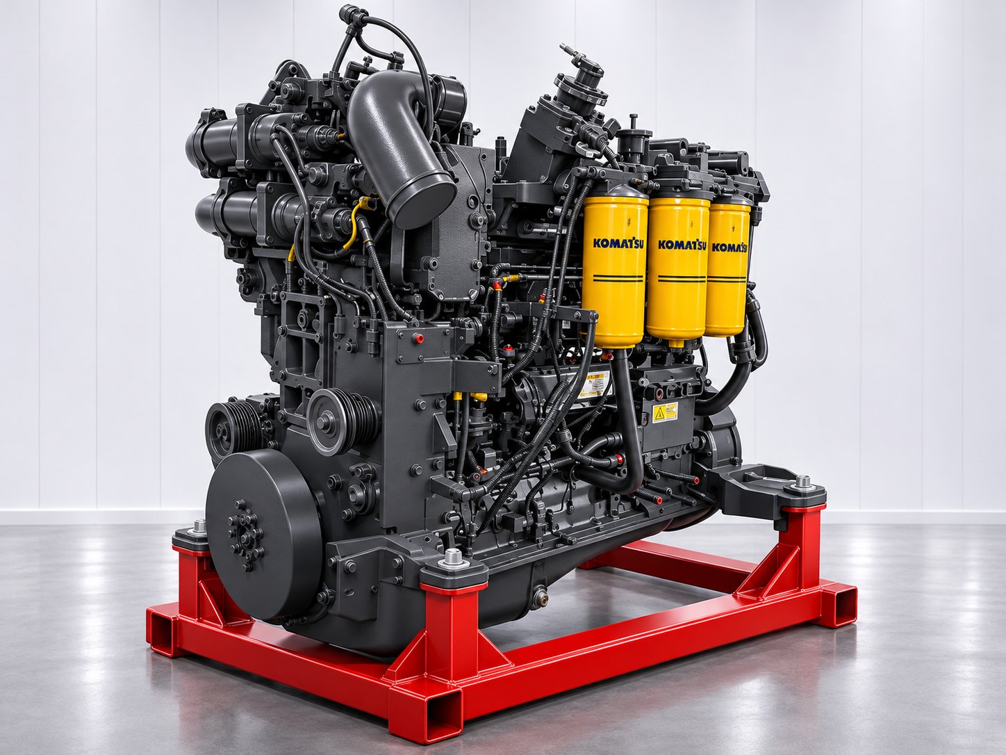
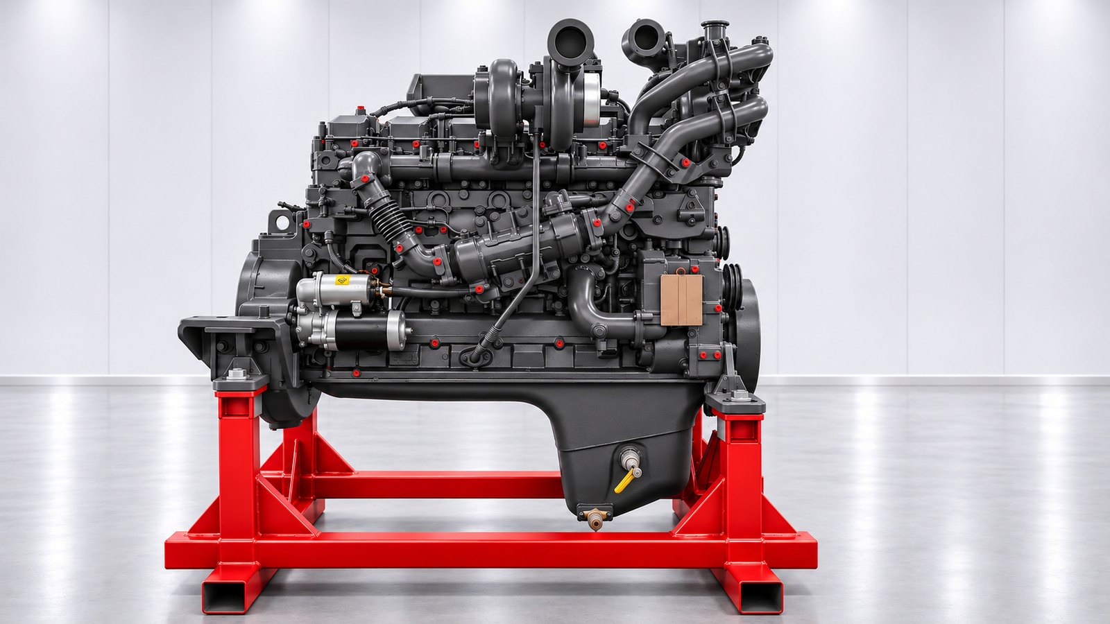
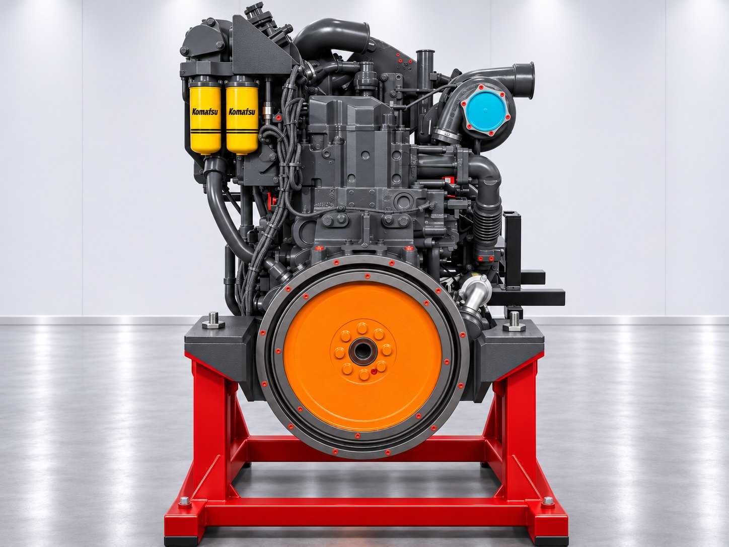
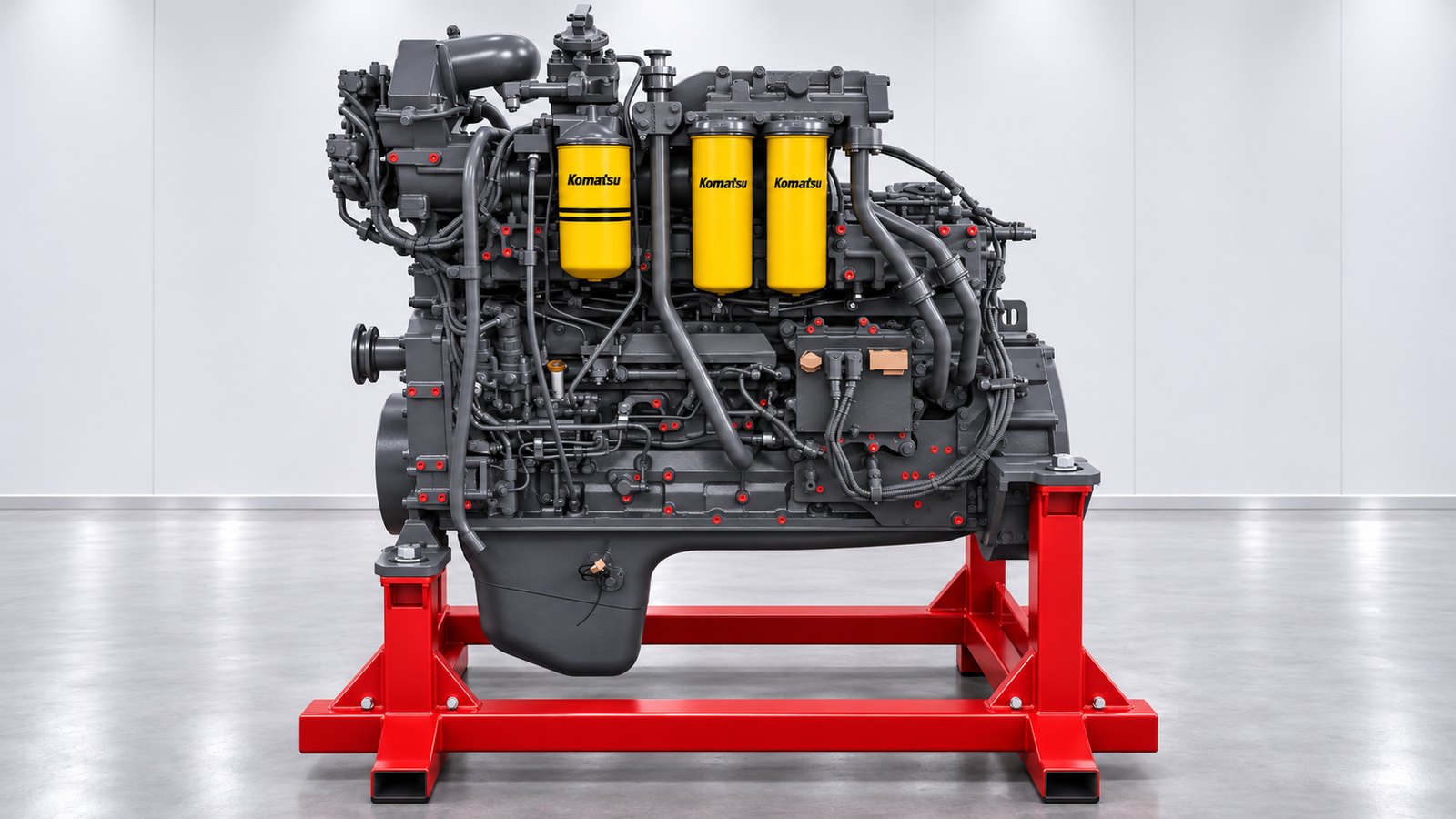
How the name reads
- S — turbocharging; AA — air-to-air charge-air cooling;
- 6D — six cylinders in line, diesel; 140 — cylinder bore in millimetres;
- E — generation designation; -5 — engine series;
- the letter after the series (-5A, -5G, -5JR) — the version for a specific machine: power, ancillaries, sometimes internal parts. The full designation with the letter and the engine serial number (ESN) are stamped on the engine data plate.
The family is simply called “6D140”. In listings this name covers the -2, -3, -5, -6 and -7 generations, but they are different engines: parts and assemblies are selected by the numbers specific to each generation (more in section 16).
A short history
The S/SA6D140 series appeared at Komatsu in 1986 and has since gone through several generations: from mechanical high-pressure pumps to electronic Common Rail systems. The 140E-5 generation is a Tier 3 engine (“ecot3”): electronic injection control with pressure up to 160 MPa, cooled exhaust gas recirculation on versions without the “R” suffix, and an improved KTR110L turbocharger. For regional versions with the “R” suffix, a version without EGR is produced.
According to Komatsu's description, the 140E-5 is the successor to the 140E-3 series: the block dimensions are retained, and the cylinder block is modified for the EGR system. The version without EGR uses two combined oil filters (the 140E-3 had one) and improved twin piston cooling jets.
2. Scale: figures worth remembering
The rated data are easier to grasp in familiar quantities. Figures from the Komatsu manual are marked as such; everything we calculated from the rated data is marked as a calculation.
- One cylinder holds about 2.54 L; the whole engine is six such cylinders, 15.24 L in total (calculation: π/4 × 0.14² × 0.165 × 6; in the manual's table the value is rounded to 15 230 cm³).
- 165 mm piston stroke. Mean piston speed is 9.9 m/s at 1 800 rpm, 10.5 m/s at 1 900 and 11.0 m/s at 2 000 rpm (calculation: 2 × stroke × speed).
- Mean effective pressure from the maximum torque of 2 170 N·m on the HD325-7 / HD405-7 is about 17.9 bar (calculated with 4π·T/V); for the PC800-8 about 18.1 bar, for the WA500-6 about 14.9 bar.
- Specific output: HD405-7 — 25.3 kW per litre of displacement (386 ÷ 15.24), WA500-6 — 17.5 kW/L.
- Dry weight of the complete engine — from 1 680 to 1 920 kg depending on the version; length — from 1 461 to 1 775 mm, width — 966–1 250 mm, height without the exhaust pipe — 1 157–2 020 mm.
- Fuel consumption at rated power — from 204 to 223 g/(kW·h) depending on the version.
- Firing order — 1-5-3-6-2-4; seven crankshaft main bearings; two oil jets cooling the piston crown for each cylinder (12 in total); four valves per cylinder (24 in total).
- Oil: fill capacity — from 45 to 58 L (of which the changeable volume is 37 to 53 L); coolant in the engine — 24–25 L.
- Fuel system: rail pressure up to 160 MPa; the safety valve opens at about 200 MPa; 71 fault codes in the controller's diagnostic table (section 26).
- Electrical: 24 V, 11 kW starter motor; 24 V alternator; on EGR versions — a separate EGR oil pump for the hydraulic valve drive.
The question “how much horsepower does the SAA6D140E-5 have?” therefore has not one figure but a table: Komatsu publishes gross power at the flywheel without the fan, and it depends on the version. Metric “horsepower” (PS) differs from the American hp by about 1.4 % as well, so figures from different brochures are compared only after checking the unit and the measurement standard.
3. Where this engine works
The SAA6D140E-5 is fitted to the machines listed below (according to the Komatsu manual for 140E-5 series engines and reference lists). The same engine works in different modes: in a truck — a long haul under load, in an excavator — matching with the hydraulic pumps, in a dozer — drawbar pull at the limit, in a loader — cycles of acceleration and loading. That is why power, controls, cooling and ancillaries differ between versions, and selecting “by cylinder bore” is not enough — the ESN is required.
| Machine | Equipment type | Power, kW (hp) / rpm | Max. torque, N·m / rpm | Version |
|---|---|---|---|---|
| D155AX-6 | Crawler dozer | 268 (360) / 1 900 | 1 834 / 1 300 | with cooled EGR |
| D155A-6 / D155A-6R | Crawler dozer | 268 (360) / 1 900 | 1 834 / 1 300 | without EGR |
| D275AX-5E0 | Crawler dozer | 337 (452) / 2 000 | 2 030 / 1 400 | with cooled EGR |
| D275A-5R | Crawler dozer | 337 (452) / 2 000 | 2 030 / 1 400 | without EGR |
| WA500-6 | Wheel loader | 266 (357) / 1 900 | 1 803 / 1 250 | with cooled EGR |
| WA500-6R | Wheel loader | 266 (357) / 1 900 | 1 803 / 1 250 | without EGR |
| HD325-7, HD405-7 | Rigid haul truck | 386 (518) / 2 000 | 2 170 / 1 400 | with cooled EGR |
| HD325-7R, HD405-7R | Rigid haul truck | 386 (518) / 2 000 | 2 170 / 1 400 | without EGR |
| HM350-2 | Articulated truck | 304 (407) / 2 000 | 1 991 / 1 400 | with cooled EGR |
| HM350-2R | Articulated truck | 304 (407) / 2 000 | 1 991 / 1 400 | without EGR |
| HM400-2, HM400-3M0 | Articulated truck | 338 (453) / 2 000 | 2 089 / 1 400 | with cooled EGR |
| HM400-2R, HM400-3R | Articulated truck | 338 (453) / 2 000 | 2 089 / 1 400 | without EGR |
| PC600-8, PC600LC-8, PC600-8E0, PC700-8E0 | Hydraulic excavator | 323 (433) / 1 800 | 1 944 / 1 400 | with cooled EGR |
| PC600-8R / R1, PC700-8R / R1 | Hydraulic excavator | 323 (433) / 1 800 | 1 944 / 1 400 | without EGR |
| PC800 / PC850-8, -8E0 | Hydraulic excavator | 370 (496) / 1 800 | 2 195 / 1 350 | with cooled EGR |
| PC800 / PC850-8R, -8R1 | Hydraulic excavator | 370 (496) / 1 800 | 2 195 / 1 350 | without EGR |
| SDG400S-6B1 (generator set) | Generator set | 357 (478) net / 1 800 | — | with cooled EGR |
The power of one machine cannot be transferred to another, even if the same base engine designation is given: the version determines the governor settings, the ancillaries and the test standards. Detailed data sheets by machine family are in section 18.
Links to machine pages in our catalogue: D155AX-6, D275AX-5E0, D275A-5R, WA500-6R, HD405-7, HD405-7R, HD325-7R, HM350-2, HM400-2, HM400-3R, PC700LC-8R, PC800-8, PC850-8R1. The engine in our applicability reference: SAA6D140E-5.
4. Complete engine, long block, short block: four levels of the assembly
The same power unit is supplied at different levels of completeness. The level chosen determines the installation time and the amount of work for the mechanic, so it should be decided before ordering.
| Assembly | Meaning | Cylinder heads | Ancillaries and systems | Who transfers the ancillaries |
|---|---|---|---|---|
| Cylinder block | A block or its assembly in a certain configuration | No | No | The customer's mechanic |
| Short block | The lower mechanical assembly of the engine | No | Per specification | The customer's mechanic |
| Long block | Mechanical assembly with heads and valve train | Yes | Partly | The customer's mechanic transfers the turbocharger, fuel system, manifolds and electronics |
| Complete engine | The whole power unit | Yes | Turbocharger, fuel system, electronics, alternator, starter motor | Not required: the engine is removed and installed as a whole |
When a complete engine is the best choice
- When wear has affected both the “mechanics” and the ancillaries: the fuel equipment, turbocharger, oil cooler, water pump.
- When the machine is standing idle and it is important to cut downtime: the engine is replaced as a whole, without transferring dozens of assemblies and re-checking each of them.
- When, after a failure with metal debris, contamination must be ruled out: in a ready-made unit the lubrication, cooling and fuel circuits have already been put in order.
- When the customer's workshop does not want to deal with diagnosing the ancillaries: the controller, sensors and engine harnesses are included.
When a long block or short block is enough. If the ancillaries are in good condition (turbocharger, high-pressure pump and injectors checked on a test bench), it is more economical to fit a long block and transfer the ancillaries: a detailed review of that level is in our article on the SAA6D140E-5 long block. Komatsu short blocks for this engine are divided into four machine groups: 6261-SE-0011 (D155A-6R, D155AX-6, D275AX-5E0, D275A-5R, HD325-7 / -7R, WA500-6 / -6R), 6261-SE-0021 (PC600-8 / -8R), 6261-SE-0031 (PC800LC-8, PC800SE-8 and R versions), 6261-SE-0041 (HM350-2 / -2R, HM400-2 / -2R).
5. Komatsu numbers: how to read RM, R and E0
Reference numbers of SAA6D140E-5 assemblies
The SAA6D140E-5 engine is listed in Komatsu catalogues at several levels. Below are the numbers that appear in parts lists and reference materials. They are given for searching and cross-checking; the unit we supply is defined by its own data plate and serial number.
| Number | Level | Comment |
|---|---|---|
RM6261-A0-0020 | Complete engine, remanufactured part number | Listed in parts lists for the WA500-6 (version -5A-01) |
RM6261-H0-0033 | Complete engine, remanufactured part number | Listed in parts lists for the D275AX-5E0 |
6261-C0-0060 | Complete engine | Listed in parts lists for the HM400-2 |
RM6261-LE-0100 | Long block, remanufactured part number | A single number for the list of machines with the SAA6D140E-5 |
RMKLBSAA6D140-03 | Long block, early catalogue revision | 11 machine models; all are also included in the RM6261-LE-0100 list |
6261-LE-0010 | Long block | Listed in parts lists for the WA500-6 |
6261-LE-0100 | Long block (number without the RM prefix) | The 6261 series corresponds to the SAA6D140E-5 |
6261-SE-0011 | Short block | D155A-6R, D155AX-6, D275AX-5E0, D275A-5R, HD325-7 / -7R, WA500-6 / -6R |
6261-SE-0021 | Short block | PC600-8, PC600-8R |
6261-SE-0031 | Short block | PC800LC-8, PC800SE-8 and R versions |
6261-SE-0041 | Short block | HM350-2 / -2R, HM400-2 / -2R |
Complete engine numbers occur for individual machines and versions; there is no single “number for the whole family” for the complete engine, so selection follows the chain “version → ESN → machine” (section 9).
What “RM”, “R” and “E0” mean: three different abbreviations
- RM at the start of a part number (
RM6261-LE-0100) is Komatsu's mark for remanufactured part numbers. - R at the end of a machine name (D155A-6R, HD405-7R, WA500-6R, PC800-8R) is a regional version, not “reman”. According to the Komatsu manual, the engines of these versions are built without the EGR system.
- E0 (D275AX-5E0, PC700-8E0) is a machine version with a Tier 3 engine; an engine with cooled EGR.
6. How a REMAN engine is made: stages and standards
REMAN is not “repair as needed” but a repeatable technological process. For the SAA6D140E-5 it rests on the dimensions, tolerances and repair methods in the Komatsu manual for the 140E-5 series (Shop Manual, the “Repair and replacement of parts” section and the standard value tables). Below are the stages and what is checked at each of them.
| Stage | What is done |
|---|---|
| 1. Receipt and identification | The model, version (-5A, -5G, -5JR…), ESN and condition of the core are recorded. The version — with EGR or without EGR (R) — and the part cut-offs by serial number are determined: the numbers of the head, bearing shells, crankshaft and fuel pump depend on them. |
| 2. Disassembly and washing | The engine is taken down to individual parts following the manual's sequence (separate procedures for the EGR and non-EGR versions); parts are cleaned, and the oil and coolant passages are flushed. |
| 3. Inspection | Each part is compared with the standard value and the limit in the dimension tables: liners (bore of groups S and L, out-of-roundness, cylindricity), main bearing housings (checked with a centring gauge arbor), crankshaft journals, camshaft, tappets, valves and guides, connecting rods and bushes, gears. |
| 4. Restoration | The methods described in the manual are applied: grinding of the head and block mating faces, valve grinding, replacement of valve guides and seats, replacement of crosshead guides, replacement of connecting rod and camshaft bushes, replacement of the flywheel ring gear and gears, grinding of the crankshaft to the undersizes of 0.25 / 0.50 / 0.75 / 1.00 mm, inspection and replacement of liner rings. |
| 5. Replacement of wear parts | Seals, gaskets, bearing shells, rings, torque-to-yield bolts (head, main bearing cap, connecting rod and flywheel bolts, with a limit on the number of uses) and other parts that must be replaced under the repair standards are renewed. |
| 6. Assembly | Assembly follows the manual's sequence, with the tightening torques from section 21, the clearances from section 20 and the gear alignment marks; valve clearances are adjusted (intake 0.35 mm, exhaust 0.57 mm on a cold engine). |
| 7. Ancillaries | The Common Rail fuel system, turbocharger, EGR system (on versions without “R”), electronics and sensors are checked and fitted according to the version; the scope is fixed in the specification. |
| 8. Testing | The engine is checked against the standard value tables (oil pressure, boost, crankcase pressure, smoke density) and the manual's run-in stages — five stages, 20 minutes (section 23). |
| 9. Documents and shipment | For each unit — a specification, a photo of the data plate and the serial number; then preservation and packing for the chosen logistics. |
The scope of operations and the list of dimensions checked are defined by the Komatsu manual and the specification of the particular unit. For each delivery we state exactly what has been done and what is included.
7. What the complete engine includes: catalogue groups
To describe the “complete engine” without ambiguity, we rely on the group structure of the engine parts catalogue: each group is an assembly with its own parts list. The table below shows which groups make up the SAA6D140E-5 power unit and which of them are optional. The group codes are taken from the engine catalogue; the parts list within a group depends on the version and ESN.
| № | Group | Catalogue code | What is included | Note |
|---|---|---|---|---|
| 1 | Air intake and air pipe | A1410 | air pipe, hoses, brackets, air cleaner housing with element and dust ejector | — |
| 2 | Turbocharger and its mounting | A1530 | KTR110L turbocharger, oil and coolant lines, fasteners | — |
| 3 | Exhaust system | A1610 | exhaust manifold, silencer, pipes | — |
| 4 | Heat shields | A1570 | exhaust system and turbocharger shields | — |
| 5 | EGR valve, EGR cooler, bypass | A1550 | EGR valve with hydraulic drive, cooler water tubes, bypass valve and air duct tubes, front engine hanger | only on versions without the “R” suffix |
| 6 | Cylinder block | A2010 | block with liners, main bearing caps, piston cooling jets | — |
| 7 | Block accessories | A2011 | plugs, tubes, sensors and brackets on the block | — |
| 8 | Crankshaft | A2310 | shaft, bearing shells, thrust half-rings, gear | — |
| 9 | Torsional vibration damper and flange | A2330 / A2370 | damper, damper flange | — |
| 10 | Pistons and connecting rods | A2350 | pistons, rings, pins, connecting rods, bearing shells, bolts | — |
| 11 | Camshaft | A2410 | shaft, gear, thrust elements | — |
| 12 | Valve train parts | A2411 | tappets, pushrods, rocker arms, crossheads | — |
| 13 | Tappet cover | A2060 | cover over the tappet area | — |
| 14 | Front gear cover | A2040 | front end cover | optional |
| 15 | Front cover accessories | A2041 | oil seals, brackets, sensors | — |
| 16 | Idler gears | A2050 | large, small and auxiliary idler gears, shafts | — |
| 17 | Front power take-off | A2610 | fan and alternator drive pulley, bearings | — |
| 18 | Flywheel housing | A2210 | housing, seals | — |
| 19 | Flywheel | A2230 | flywheel, ring gear | — |
| 20 | Oil sump | A2110 | sump, gasket, plugs | — |
| 21 | Engine mounts | A2250 | brackets and mounts | — |
| 22 | Oil pump | A3010 | gear pump with relief valves | — |
| 23 | Oil cooler | A3310 | plate-type cooler with thermostatic valve | optional |
| 24 | Fuel brackets and lines | A4030 | brackets, fuel tubes | — |
| 25 | Fuel filter and priming pump | A4110 | main filter, manual or electric priming pump | — |
| 26 | Fuel filter cartridges | A4119 / A4159 | main filter and pre-filter with water separator | — |
| 27 | High-pressure fuel pump | A4010 | DENSO ECD-U2 pump | — |
| 28 | Fuel pump lubricator | A4060 | supply of engine oil to lubricate the pump | — |
| 29 | Engine controller (ECU) | A4710 | controller with brackets and fuel cooling | — |
| 30 | Injectors | A4210 | electronic Common Rail injectors | — |
| 31 | Fuel drain line | A4230 | return tubes | — |
| 32 | Water pump | A5010 | centrifugal pump with gear drive | optional |
| 33 | Corrosion resistor | A5210 | cartridge with inhibitor | depending on the version |
| 34 | Alternator | A6010 | 24 V, 60 / 75 / 90 A variants | — |
| 35 | Starter motor | A6210 | 24 V, 11 kW | — |
| 36 | Engine wiring | A6810 | harnesses, connectors, sensors | — |
| 37 | Plates | A9810 | identification and warning plates | — |
The optional assemblies — the front gear cover, oil cooler and water pump — are, by agreement in the specification, either supplied as part of the unit or transferred from the old engine. The corrosion resistor (inhibitor cartridge) depends on the version.
What belongs to the machine, not the engine
The complete engine does not include the assemblies that belong to the machine itself: the radiator and the air-to-air charge-air cooler, the fan and its drive, the excavator's hydraulic pumps, air ducts and the exhaust pipe, the frame and mounts, the machine's cable network and the panel. We fix the boundary in the specification: for each version it states what is on the unit and what stays on the machine.
Engine electrical equipment
- Alternator: 24 V; the catalogue lists 60, 75 and 90 A versions, as well as versions to EU requirements and with a hardened pulley.
- Starter motor: 24 V, 11 kW.
- Batteries: per the machine specification, 12 V × 2 (170 Ah) — they belong to the machine.
- Engine controller (ECU): mounted on the engine and cooled by fuel; versions for US standards (EPA Tier 3) and other regions.
8. Configurations by machine family
The complete engine is not a single configuration. Below are the main differences between the families according to the manual and the catalogue; the exact scope of each unit is stated in its specification.
| Family | Engine versions | EGR | KTR110L turbocharger | Air cleaner | Fan | Oil: fill / changeable, L |
|---|---|---|---|---|---|---|
| PC600 / PC700-8 excavators | -5B, -5B-01 (+ R versions) | Yes / no (R) | Air-cooled casing; water-cooled optional | Cyclone with ejector (FRG) | Hydraulic | 48 / 40 |
| PC800 / PC850-8 excavators | -5F, -5FR, -5M (+ R) | Yes / no (R) | Water-cooled casing — standard | Cyclone with ejector (FRG) | Hydraulic | 58 / 53 |
| D155AX-6, D155A-6R dozers | -5G, -5GR-W | Yes / no (R) | Water-cooled casing — standard for D155AX | Komaclone multi-cyclone, type ERB | Per machine | 45 / 37 |
| D275AX-5E0, D275A-5R dozers | -5AH (D275A-5R); for D275AX-5E0 — per the data plate | Yes / no (R) | Water-cooled casing — standard for D275AX | Komaclone multi-cyclone, type ERB | Per machine | 58 / 50 |
| WA500-6 / -6R loader | -5A, -5A-01, -5AR | Yes / no (R) | Air-cooled casing; water-cooled optional | Cyclone with ejector (FRG) | Per machine | 45 / 37 |
| HD325-7 / HD405-7 haul trucks | -5D, -5DR | Yes / no (R) | Air-cooled casing; water-cooled optional | Cyclone with ejector (FRG) | Engine-driven | 58 / 50 |
| HM350-2, HM400-2 / -3 articulated trucks | -5E, -5ER, -5CR, -5JR | Yes / no (R) | Air-cooled casing; water-cooled optional | Cyclone with ejector (FRG) | Engine-driven | 58 / 50 |
| SDG400S-6B1 generator set | — | Yes | By version | By version | Engine-driven | 82 / 73 |
Versions are given according to the catalogue and the manual (more in section 16). On excavators the fan drive is hydraulic, on haul trucks and the generator set it is driven by the engine; on dozers and the loader the drive arrangement is determined by the machine.
9. How to select a complete engine: seven steps
Selection is a chain of checks: reference number → exact lettered engine version → Engine S/N → machine model → Machine S/N → check of revisions and cut-offs by serial number → unit specification. Engine S/N and Machine S/N are different identifiers: the engine serial number belongs to the power unit, the machine number to the base machine.
What the buyer should prepare
- The full engine name — SAA6D140E-5 with the version letter (-5A, -5G, -5JR…).
- Engine S/N — a photo of the data plate with a legible number.
- The machine model with its suffix: HD405-7R, not just HD405; D275AX-5E0, not D275.
- Machine S/N — the machine serial number.
- The engine version — with or without EGR; this can be seen from the machine suffix and from the presence of the EGR cooler and valve on the engine.
- The required level of assembly — short block, long block or complete engine.
- Photos of the old engine from the front and both sides, and photos of the controller connectors — this makes it easier to check the ancillaries and harnesses.
Neighbouring generations are separate engines. For the SA6D140E-3 and SAA6D140E-3 the long blocks are RM6218-LE-0100 and RM6218-LE-0110, for the SAA6D140E-6 (HM400-3, D155AX-7, WA500-7) — RM6262-LE-0100, for the S6D140E-2 and SA6D140E-2 — RM621B-LE-0100. A SAA6D140E-5 engine is selected for the SAA6D140E-5.
The same engine for the D155AX-6 and HM400-2? The engine base is the same — SAA6D140E-5 — but the versions differ in letter, ancillaries and serial ranges, so a complete engine is always selected for the specific machine from the data plate.
10. Our complete REMAN SAA6D140E-5 engine
CATKOMPARTS supplies spare parts and assemblies for heavy equipment. The complete REMAN SAA6D140E-5 engine is a Komatsu product that we supply: we select the version for your machine, agree the scope, and prepare the specification and a photo of the unit's data plate before payment. The engine page in our reference: SAA6D140E-5; the long-block level is available as a separate product page — REMAN long block.
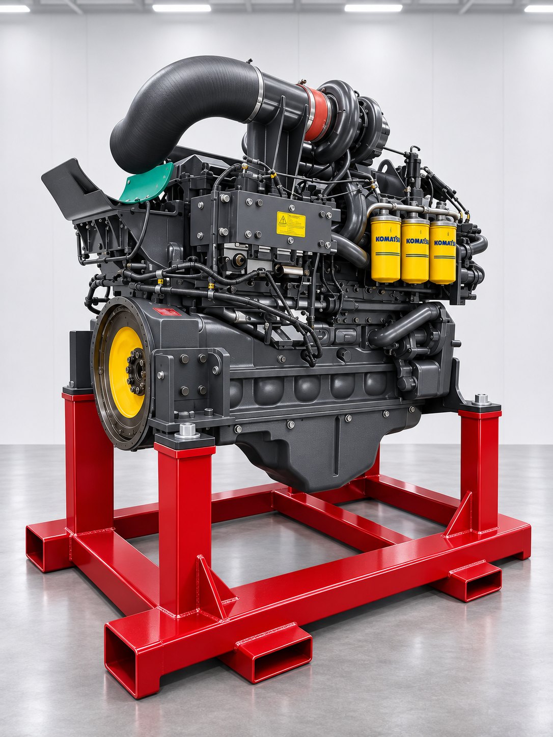
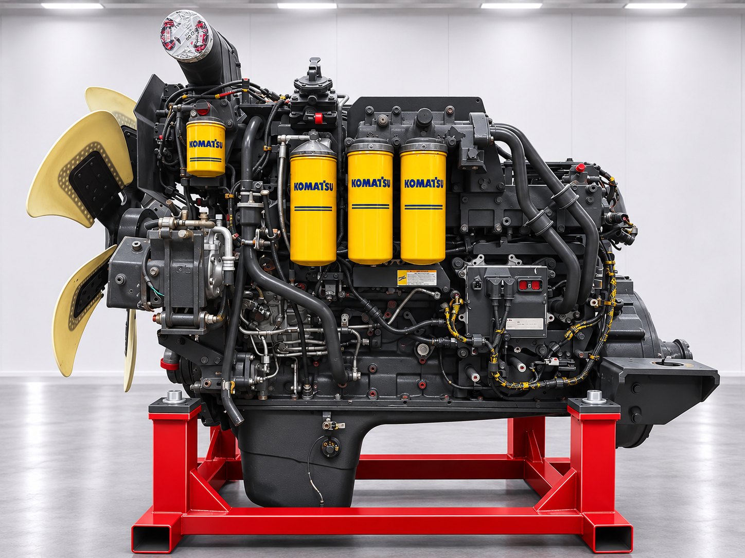
Engine product page: Komatsu SAA6D140E-5 REMAN complete engine — available for pre-order. Its applicability covers the machines listed in section 3. The same engine base at the level of the mechanical core is the REMAN long block.
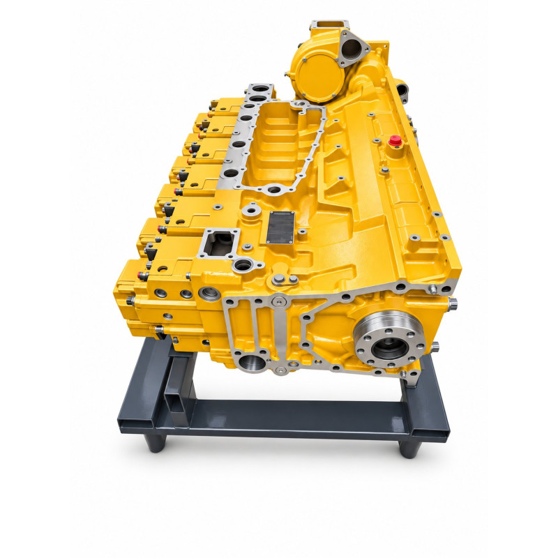
- Specification before payment: the scope of supply, version, optional assemblies and the “engine / machine” boundary are fixed in writing.
- Unit identification: a photo of the data plate and the serial number of each engine — on request and in the specification.
- Reference numbers (
RM6261-A0-0020,RM6261-H0-0033,6261-C0-0060) are given for cross-checking and searching; the unit supplied is defined by its own data plate. - Lead time and pre-order: the complete engine is available for pre-order. Arrivals in February 2027: 1 pc to Brazil (Guarulhos warehouse, São Paulo) and 1 pc to Dubai (from the central warehouse). For the long block, the first batch is 3 units, expected in February 2027 in Guarulhos.
- Brazil: pickup from the warehouse in Guarulhos or delivery within the country. Export: handover to your logistics company. Russia: delivery by agreement as far as the customs port (Vladivostok or St Petersburg).
- Payment: payment first, then shipment; for Russia — 100 % prepayment.
- Warranty is agreed individually and recorded in the specification and the invoice.
- How to order: send a photo of the engine data plate (full model with the letter and the ESN), the machine model and serial number and photos of the old engine — through the form on the site or on WhatsApp.
If you need individual assemblies for your own build, the catalogue has parts for this engine: cylinder block 6261-21-1110, cylinder head assembly 6261-11-1110, crankshaft assembly 6261-31-1210, camshaft assembly 6210-41-1112, connecting rod 6261-31-3100. The catalogue numbers are given for identification; check them using the chain from section 9.
Part II. For the engineer and the mechanic: design of the complete engine
This part describes the engine by system, in the order in which the Komatsu 140E-5 manual sets out the design and maintenance standards (SEN00081, SEN00082): intake and exhaust, the main moving parts, lubrication, the fuel system, cooling, ancillaries and electrical equipment. For a complete engine, knowledge of the systems matters because their serviceability is checked on the unit as a whole.
11. Block, crank mechanism and valve train
11.1. Cylinder block and liners
- A block with seven main bearing journals for the crankshaft and seven camshaft bearings (the camshaft is mounted high — “high cam”). The main bearing cap bolts are tightened into the plastic range (with an angle turn); the number of uses of the bolts is limited — no more than five tightenings.
- Wet liners: the coolant washes the liner directly. The inner surface is plateau-honed and soft-nitrided. Sealing: at the top — a “clevis seal” gasket, in the middle — an ethylene-propylene rubber (EPR) ring, at the bottom — a silicone rubber ring.
- Two oil jets cooling the piston crown for each cylinder (12 in total). On versions without EGR — improved twin piston cooling jets.
- For the EGR version the block is partly modified for cooled recirculation; the block dimensions are retained.
- The front oil seal is single-lip with a dust lip.
11.2. Crankshaft, connecting rods, pistons
- The crankshaft is a closed-die forging; the journals and fillets are strengthened by induction hardening; seven main journals 120 mm in diameter and crankpin journals 90 mm in diameter. Journal undersizes: 0.25 / 0.50 / 0.75 / 1.00 mm (section 20). The crankshaft gear has 36 teeth; at the front end — the torsional vibration damper.
- The connecting rod is a forging; the cap is tightened into the plastic range, with an oil hole. The mass difference between connecting rods in one engine is no more than 154 g.
- The piston is made of special spheroidal graphite cast iron (FCD) with a re-entrant combustion chamber. Rings: top — double-sided “keystone” with an internal relief, barrel-faced running surface, hard chrome; second — double-sided “keystone” with an internal relief, tapered surface, hard chrome; oil control — steel M-type with a coil expander, nitrided.
- Flywheel and flywheel housing: ring gear for the starter motor; the face and radial runout of the housing and flywheel is limited to 0.20 mm (flywheel radial runout — 0.13 mm).
- The torsional vibration damper is mounted on the front end of the crankshaft with a pulley bolt tightened to 275 N·m (245–309).
11.3. Cylinder heads and valve train
- The heads are separate — one head per cylinder (six in all), with four valves per cylinder (two intake and two exhaust). Direct injection. Centralised cooling of the bridge between the valves and of the injector area. The valve seats are pressed in (intake and exhaust). The injector is of the “dry” type — without a sleeve.
- The head bolts are tightened into the plastic range, with a maximum of five uses; for each use a punch mark is made on the bolt. The head cover is sealed with an O-ring.
- The camshaft is made from drawn steel stock; the journals and lobes are induction-hardened. It is driven through roller tappets, pushrods, rocker arms and crossheads, which open two valves at once.
- Valve clearances on a cold engine: intake 0.35 mm, exhaust 0.57 mm (tolerance ±0.02).
11.4. Gear drive
The valve timing and the ancillary drives are gear-driven. The tooth counts are given in the table; the alignment marks are: crankshaft — large idler; small idler — fuel pump gear; small idler — camshaft gear. Backlash in mesh is in section 20.
| Gear | Number of teeth | Drive |
|---|---|---|
| Crankshaft | 36 | — |
| Large idler | 60 | — |
| Small idler | 40 | — |
| Auxiliary idler | 42 | — |
| Camshaft | 48 | — |
| High-pressure fuel pump | 48 | ECD-U2 |
| Oil pump | 20 | 1.8 crankshaft revolutions |
| Water pump | 23 | 1.56 crankshaft revolutions |
| Air compressor | 14 | option |
| EGR oil pump | 22 | EGR version only; 1.09 crankshaft revolutions |
12. Air, boost, exhaust and EGR
The Komatsu manual describes the “Air intake and exhaust unit” separately: the air cleaner, turbocharger, charge-air cooler, silencer and EGR system. The path of the air and gases on the EGR version is shown in the diagram.
12.1. Air cleaner
The D155AX-6, D155A-6, D275AX-5E0 and D275A-5R dozers use an ERB-type air cleaner — the Komaclone multi-cyclone with automatic dust removal by the exhaust ejector. On the other machines — a cyclone filter with an evacuator valve (FRG). Intake restriction is no more than 3.73 kPa; the replacement criterion is 7.47 kPa.
12.2. Komatsu KTR110L turbocharger
The KTR110L is an improved version of the KTR110 with a more efficient compressor wheel and an improved shaft. The air-cooled bearing housing version measures 308 × 305 × 287 mm and weighs 24 kg; the water-cooled version weighs 28 kg (standard for the D155AX, D275AX and PC800; optional on other machines). Boost pressure at rated power of a new engine is 85 to 184 kPa depending on the version (section 22).
12.3. Charge-air cooler and silencer
The charge-air cooler is air-to-air and is located on the machine. The charge-air temperature is monitored by a controller sensor (codes 153 / 154). The silencer is described in the manual in the “Air intake and exhaust unit” section; exhaust pressure at rated power is 92–172 kPa depending on the version.
12.4. EGR system (versions without “R”)
- The EGR cooler made of corrugated stainless steel tubes cools the recirculated gases with engine coolant.
- The EGR valve is hydraulically driven and electronically controlled: the controller operates a solenoid valve, and the actuator receives oil from a separate EGR oil pump.
- The bypass circuit has a Venturi tube and a bypass valve; the travel of the EGR and bypass valves is monitored by position sensors, and the EGR inlet pressure by a separate sensor.
- The valve drive pressure is at least 1.18 MPa at low idle and 1.43 MPa at high idle.
- The controller diagnoses the EGR valve (codes 1228, 1625, 2271, 2272, 2351, 2352), the bypass valve (1626–1632) and the EGR inlet pressure sensor (1642, 1653) — section 26.
- On “R” versions these assemblies are absent; the engine is 69–75 kg lighter and runs at a lower boost pressure.
13. Common Rail (CRI) fuel system
The manual describes the fuel system over 35 pages: the CRI diagram, general description, fuel lines, fuel cooler, filters, priming pumps and controller cooling. Below are the composition and principle of operation according to the manual and the controller diagnostic table.
13.1. Components
- The DENSO ECD-U2 high-pressure pump is lubricated under pressure with engine oil (the “Fuel supply pump lubricator” assembly in the catalogue) and driven by the fuel pump gear (48 teeth). The pressure is regulated by two valves — PCV1 and PCV2: the controller diagnoses their circuits (codes 271–274) and the delivery of pumps 1 and 2 (codes 559 and 2249).
- The rail has a pressure sensor: the controller monitors overpressure (codes 449, 553), and the range and signal of the sensor (451, 452, 554).
- The electronic injectors — one per cylinder, each controlled by a separate controller channel. The fault codes follow the firing order: No. 1 (code 322), No. 5 (323), No. 3 (324), No. 6 (325), No. 2 (331), No. 4 (332).
- The maximum working pressure has been raised from 120 MPa (Tier 2) to 160 MPa; the pressure safety valve opens at about 200 MPa.
- The fuel cooler (air-cooled) has 23 plates and 2.12 m²; the main fuel filter is 1.06 m² (single or twin cartridge) and the pre-filter with water separator is 1.06 m²; the priming pump is manual (diaphragm) or electric; the engine controller is cooled by fuel.
- The drain line returns excess fuel from the injectors and the pump; the drain flow and leakage is one of the diagnostic tests (section 28).
| Sequence in the cycle | Cylinder | Injector fault code | Code name |
|---|---|---|---|
| 1st | № 1 | 322 | Injector #1 System Open/Short Error |
| 2nd | № 5 | 323 | Injector #5 System Open/Short Error |
| 3rd | № 3 | 324 | Injector #3 System Open/Short Error |
| 4th | № 6 | 325 | Injector #6 System Open/Short Error |
| 5th | № 2 | 331 | Injector #2 System Open/Short Error |
| 6th | № 4 | 332 | Injector #4 System Open/Short Error |
Working on the high-pressure fuel system. The manual sets out separate procedures: rules for handling the assemblies, releasing the residual pressure before disassembly, checking the fuel pressure, the cylinder cut-out mode, cranking without injection, checking the drain flow and leakage, bleeding air and leak testing. The work is carried out only according to the manual and only on a stopped engine with the residual pressure released as per the procedure.
14. Lubrication, cooling and engine accessories
14.1. Lubrication system
- The oil pump is gear-type (drive gear 20 teeth, speed 1.8 crankshaft revolutions). The main relief valve opens at a pressure of 600 ± 50 kPa, the auxiliary one at 1 000 ± 50 kPa.
- Full-flow combined filters, each with 0.44 m² of filter area; the filter safety valve opens at 343 ± 19.6 kPa.
- The SAA6D140E-5 oil cooler: 15 plates (layers), heat transfer area 1.23 m², heat transfer of at least 39 800 kcal/h; the thermostatic valve opens at 85 ± 1.5 °C and is fully open at 100 °C (lift 8 mm).
- On the EGR version there is a separate EGR oil pump (gear-type, speed 1.09 crankshaft revolutions, drive gear 22 teeth; relief valves 1 430 ± 100 and 1 800 ± 150 kPa), which hydraulically drives the EGR valve and the bypass valve.
- Oil is supplied to the galleries, crankshaft, camshaft, rocker arms, piston cooling jets, gears, high-pressure pump (lubrication) and turbocharger.
14.2. Cooling system
- A centrifugal water pump with gear drive (23 teeth), speed 1.56 crankshaft revolutions, delivery 785 L/min, head of at least 18.5 m.
- The thermostat begins to open at 76.5 ± 2 °C and is fully open at 90 °C (lift of at least 9 mm).
- The fan is hydraulic (excavators) or engine-driven (haul trucks, generator set); the drive and belt tension are checked according to the manual (section 28).
- The corrosion resistor with inhibitor depends on the version (400, 600 or 1 000 g).
- Coolant in the engine — 24–25 L (on the generator set with a radiator — 53 L).
14.3. Front power take-off, alternator, starter motor, starting aid
- Front power take-off (Front PTO): fan and alternator drive pulley with bearings; the catalogue lists a version with a hardened pulley.
- The alternator is 24 V, 60 / 75 / 90 A (versions to EU requirements and with a hardened pulley); the belt tension is checked according to the manual.
- The starter motor is 24 V, 11 kW. Cranking speed — at least 110 rpm at 0 °C without starting aids and 85 rpm at −20 °C with starting aids.
- Intake air pre-heating — the controller monitors the heater relay (codes 2555 and 2556).
15. Engine electronics: controller, sensors, actuators
The engine controller (ECU) is mounted on the engine itself, is cooled by fuel and automatically compensates for altitude using the atmospheric pressure sensor. It is connected to the machine by the KOMNET network (network error — code 1633). The list of sensors and actuators follows from the manual's diagnostic code table.
| Sensor | What it measures | Fault codes |
|---|---|---|
| Ne (crankshaft speed) | Crankshaft speed and position | 115, 238, 689 |
| Bkup (backup, pump camshaft) | Phase and backup speed signal (7 pulses per 2 revolutions) | 115, 731, 778 |
| Boost pressure | Air pressure after the compressor | 122, 123 |
| Atmospheric pressure | Altitude correction | 221, 222 |
| Charge-air temperature | Temperature after the cooler | 153, 154 |
| Coolant temperature | Thermal state of the engine | 144, 145 |
| Oil pressure | Pressure in the main gallery | 135, 141 |
| Fuel temperature | Temperature in the fuel system | 263, 265 |
| Rail pressure | Common Rail pressure | 451, 452, 554 |
| Pedal / throttle control sensor | Load demanded by the operator | 131, 132, 2185, 2186 |
| EGR inlet pressure | Recirculation monitoring | 1642, 1653 |
| EGR and bypass valve travel | Valve position | 1631, 1632, 2271, 2272 |
| Idle confirmation switch | Idle identification | 431, 432 |
| Assembly | Codes | Purpose |
|---|---|---|
| Injectors No. 1–6 | 322–332, 351 | Fuel injection by cylinder; injector control circuit |
| PCV1 and PCV2 valves | 271–274 | Rail pressure regulation |
| EGR solenoid valve | 2351, 2352 | Control of the EGR valve hydraulic drive |
| Bypass solenoid valve | 1626, 1627 | Control of the bypass valve |
| Intake air heater relay | 2555, 2556 | Starting aid |
| Sensor supply 1 and 2 | 187, 227, 352, 386 | Sensor supply voltage |
| Controller power supply | 441, 442 | Supply voltage |
15.1. Engine protection functions
The controller limits engine operation in dangerous conditions: low oil pressure — torque limitation (code (143) / B@BAZG) and speed limitation (code (415) / B@BAZG); engine overheating (code (146) / B@BCNS); overspeed (code 234). More in section 26.
15.2. Code indication
The manual describes how a fault code is shown by the diagnostic lamps and the general search rule: first look at the code (E-mode), and if there is no code, then at the symptom (S-mode). The diagnostic table has 71 E-mode entries and 16 S-mode symptoms (sections 26 and 27).
16. Versions: letters, serial numbers, EGR and “R”, generations
16.1. What -5A, -5G, -5JR… mean
The letter after “-5” defines the version for the machine: power, ancillaries, sometimes internal parts. The serial number series 530xxx, 535xxx and 536xxx belong to the “first” -5 versions, the 63xxxx series to versions with the R suffix. The table is a guide to the versions and the starting engine serial numbers according to parts catalogues; the exact range for your engine is confirmed from the data plate.
| Version | Machines | Starting Engine S/N |
|---|---|---|
-5A | WA500-6 | 535838-UP |
-5AR | WA500-6R | 630345-UP |
-5AH | D275A-5R | 630336-UP |
-5B | PC600-8E0, PC600LC-8E0, PC650LC-8E0, PC700LC-8E0 | 536098-UP |
-5CR | HM400-2R | 630276-UP |
-5D | HD325-7, HD405-7 | 530015-UP |
-5DR | HD325-7R, HD405-7R | 630332-UP |
-5E | HM350-2 | 535052-UP |
-5ER | HM350-2R | 630228-UP |
-5F | PC800-8E0, PC800LC-8E0 | 536267-UP |
-5G | D155AX-6 | 535751-UP |
-5JR | HM400-3R | 631995-UP |
Longer designations such as SAA6D140E-5A-01, -5B-01, -5FR, -5GR-W also occur: these are version revisions, and they too are confirmed from the data plate. The version -5M (PC800 / PC850-8) also appears in the names of parts lists.
16.2. What “535751-UP” means
“535751-UP” is a range starting from the stated engine serial number and continuing upwards within the conditions of the particular publication. Within the catalogue, individual lines may have their own conditions: “from–to”, “and above”, a replacement number, a note. So “UP” is read together with the version and the diagram, and the reliable way is to check against your Engine S/N.
16.3. Versions without “R” and with “R”: how the engines differ
| Feature | Without “R” (with EGR) | With “R” (without EGR) |
|---|---|---|
| Exhaust gas recirculation | Cooled: EGR cooler, hydraulically driven valve, Venturi bypass, EGR oil pump | None — “EGR-less” in the manual (separate weight and gear tables) |
| Emission class per specifications | Tier 3 / Stage 3A | Tier 2 / Stage 2 (or equivalent) |
| Dry engine weight | 1 750–1 920 kg | 1 680–1 850 kg (69–75 kg lighter) |
| Boost pressure at rated power, new engine (min.) | 116–184 kPa (by machine) | 85–135 kPa (by machine) |
| Disassembly and assembly sequence in the manual | SEN00157 (with EGR) | SEN00158 (EGR-less) |
| EGR diagnostic codes | 1228, 1625–1632, 1642, 1653, 2271, 2272, 2351, 2352 | Not applicable |
“R” at the end of a machine name is a regional version, and not “reman”. The RM prefix at the start of a catalogue number (RM6261-LE-0100) is the mark of a remanufactured part number; that is a different designation.
16.4. 6D140 generations: -2, -3, -5, -6, -7
Listings include the S6D140E-2, SA6D140E-3, SDA6D140E-3, SAA6D140E-5, -6 and -7. These are different engines with their own assemblies. The same machine received different generations in different years, so the final match is determined from the serial numbers of the machine and the engine.
| Generation | Machines | Remanufactured long block |
|---|---|---|
| S6D140E-2 and SA6D140E-2 (-2A-6, -2B-6, -2C-6) | D155A-5, D155AX-3, GD825A-2, some WA500-3 | RM621B-LE-0100 |
| SA6D140E-3 and SAA6D140E-3 | D155AX-5, PC600-6/-7, PC750-6/-7, PC800-6/-7, PC1800-6, HD325-6, HD405-6, HM350-1, HM400-1, some WA500-3 | RM6218-LE-0100, RM6218-LE-0110 |
| SDA6D140E-3 | D275A-5, D275AX-5 (without the E0 suffix) | — |
| SAA6D140E-5 | D155AX-6, D155A-6R, D275AX-5E0, D275A-5R, HD325-7 / HD405-7 (+R), HM350-2 (+R), HM400-2 (+R), HM400-3M0 / -3R, PC600-8, PC700-8, PC800 / PC850-8 (+R), WA500-6 / -6R | RM6261-LE-0100 |
| SAA6D140E-6 | HM400-3, D155AX-7, WA500-7 | RM6262-LE-0100 |
| SAA6D140E-7 | WA500-8 | — |
According to Komatsu materials for service engineers, the D155A-5 has the SA6D140E-2 (302 hp), the D155AX-5 has the SA6D140E-3 (310 hp), and the D155AX-6 moved to the SAA6D140E-5. Do not confuse the 6D140 with other large Komatsu engines: the D375A dozer runs on the SAA6D170E-5 (cylinder bore 170 mm) — a detailed review is in our article on the SAA6D170E-5, and the D475A dozer on the V-type SAA12V140E-3 with cylinders of the same 140 mm bore but a completely different block.
17. Specifications by machine
All values are from the 140E-5 engine specification table (Komatsu manual, SEN00079): gross power at the flywheel without the fan. Power, torque and idle speeds are set by the version, not by “the engine in general”. For comparison, according to machine brochures net power is: D155AX-6 — 264 kW (1 900 rpm), D275AX-5E0 — 335 kW (2 000), WA500-6 — 263 kW (1 900), PC800-8 — 363 kW (1 800), HM400-3R — 334 kW (2 000).
| Machine | Type | Version | Power, kW (hp) / rpm | Max. torque, N·m (kgf·m) / rpm | Idle: max. / min., rpm | Fuel consumption, g/(kW·h) | Dry weight, kg | Length × width × height, mm | Oil: fill (changeable volume), L | Coolant, L |
|---|---|---|---|---|---|---|---|---|---|---|
| PC600-8 / PC600LC-8 / -8E0, PC700-8E0 / LC-8E0 | Excavator | EGR | 323 (433.3) / 1 800 | 1 944 (198.4) / 1 400 | 1 950 ± 50 / 800 ± 25 | 209 | 1 845 | 1 494 × 1 151 × 1 467 | 48 (40) | 24 |
| PC600-8R / R1, PC700-8R / R1 | Excavator | without EGR | 323 (433.3) / 1 800 | 1 944 (198.4) / 1 400 | 1 950 ± 50 / 800 ± 25 | 205 | 1 770 | 1 482 × 1 191 × 1 467 | 48 (40) | 24 |
| PC800 / PC850-8, -8E0 | Excavator | EGR | 370 (496.4) / 1 800 | 2 195 (223.8) / 1 350 | 1 980 ± 50 / 825 ± 25 | 204 | 1 920 | 1 762 × 1 176 × 1 686 | 58 (53) | 25 |
| PC800 / PC850-8R, -8R1 | Excavator | without EGR | 370 (496.4) / 1 800 | 2 195 (223.8) / 1 350 | 1 980 ± 50 / 825 ± 25 | 204 | 1 850 | 1 718 × 1 176 × 1 686 | 58 (53) | 25 |
| D155AX-6 | Dozer | EGR | 268 (359.9) / 1 900 | 1 834 (187.0) / 1 300 | 2 100 (0/−50) / 740 (+40/0) | 215 | 1 800 | 1 477 × 1 109 × 1 157 | 45 (37) | 25 |
| D155A-6 / D155A-6R | Dozer | without EGR | 268 (359.9) / 1 900 | 1 834 (187.0) / 1 300 | 2 100 (0/−50) / 740 (+40/0) | 215 | 1 725 | 1 461 × 1 109 × 1 157 | 45 (37) | 25 |
| D275AX-5E0 | Dozer | EGR | 337 (451.6) / 2 000 | 2 030 (207.0) / 1 400 | 2 200 ± 50 / 700 ± 50 | 218 | 1 869 | 1 477 × 966 × 2 020 | 58 (50) | 25 |
| D275A-5R | Dozer | without EGR | 337 (451.6) / 2 000 | 2 030 (207.0) / 1 400 | 2 200 ± 50 / 700 ± 50 | 215 | 1 800 | 1 461 × 966 × 2 020 | 58 (50) | 25 |
| WA500-6 | Loader | EGR | 266 (356.9) / 1 900 | 1 803 (184.0) / 1 250 | 2 150 ± 50 / 700 ± 25 | 216.2 | 1 750 | 1 477 × 1 094 × 1 435 | 45 (37) | 25 |
| WA500-6R | Loader | without EGR | 266 (356.9) / 1 900 | 1 803 (184.0) / 1 250 | 2 150 ± 50 / 700 ± 25 | 211.4 | 1 680 | 1 461 × 1 094 × 1 435 | 45 (37) | 25 |
| HD325-7 / HD405-7 | Rigid haul truck | EGR | 386 (517.7) / 2 000 | 2 170 (221.3) / 1 400 | 2 300 ± 25 / 725 ± 25 | 212 | 1 810 | 1 775 × 1 009 × 1 604 | 58 (50) | 25 |
| HD325-7R / HD405-7R | Rigid haul truck | without EGR | 386 (517.7) / 2 000 | 2 170 (221.3) / 1 400 | 2 300 ± 25 / 725 ± 25 | 207 | 1 740 | 1 775 × 1 009 × 1 604 | 58 (50) | 25 |
| HM350-2 | Articulated truck | EGR | 304 (407.2) / 2 000 | 1 991 (203.0) / 1 400 | 2 200 (+50/0) / 725 ± 25 | 223 | 1 820 | 1 724 × 1 250 × 1 496 | 58 (50) | 25 |
| HM350-2R | Articulated truck | without EGR | 304 (407.2) / 2 000 | 1 991 (203.0) / 1 400 | 2 200 (+50/0) / 725 ± 25 | 222 | 1 750 | 1 724 × 1 250 × 1 496 | 58 (50) | 25 |
| HM400-2 / HM400-3M0 | Articulated truck | EGR | 338 (452.6) / 2 000 | 2 089 (213.0) / 1 400 | 2 200 (+50/0) / 725 ± 25 | 213 | 1 820 | 1 724 × 1 250 × 1 496 | 58 (50) | 25 |
| HM400-2R / HM400-3R | Articulated truck | without EGR | 338 (452.6) / 2 000 | 2 089 (213.0) / 1 400 | 2 200 (+50/0) / 725 ± 25 | 218 | 1 750 | 1 724 × 1 250 × 1 496 | 58 (50) | 25 |
| SDG400S-6B1 (generator set, net) | Generator set | EGR | 357 (478) / 1 800 | — | 1 890 ± 50 / 875 ± 25 | 222 | 1 950 | 1 785 × 1 242 × 1 523 | 82 (73) | 53 |
Height is without the exhaust pipe. Common to all versions: 6 cylinders 140 × 165 mm, 15.24 L, firing order 1-5-3-6-2-4, electronic governor (DENSO ECD-U2 fuel pump), KOMATSU KTR110L turbocharger, air-to-air charge-air cooling; versions without “R” have cooled EGR. For the SDG400S-6B1 generator set the power is given as net.
17.1. Calculated figures (our calculation from the rated data)
These values help to understand the load on the engine and to compare versions with each other. They are not manufacturer figures but calculations from the rated data: displacement from bore and stroke, mean effective pressure with the formula 4π·T/V, mean piston speed as 2 × stroke × speed, torque at rated speed as power divided by angular velocity.
| Machine | Mean effective pressure (BMEP) from max. torque, bar | Mean piston speed at rated speed, m/s | Specific output, kW/L | Torque at rated speed, N·m | Torque back-up (peak to rated) |
|---|---|---|---|---|---|
| HD325 / HD405-7 | 17.9 | 11.0 | 25.3 | 1 843 | 18 % |
| PC800 / PC850-8 | 18.1 | 9.9 | 24.3 | 1 963 | 12 % |
| HM400-2 / -3 | 17.2 | 11.0 | 22.2 | 1 614 | 29 % |
| D275AX-5E0 / D275A-5R | 16.7 | 11.0 | 22.1 | 1 609 | 26 % |
| PC600 / PC700-8 | 16.0 | 9.9 | 21.2 | 1 714 | 13 % |
| HM350-2 | 16.4 | 11.0 | 19.9 | 1 451 | 37 % |
| D155AX-6 / D155A-6 | 15.1 | 10.4 | 17.6 | 1 347 | 36 % |
| WA500-6 / -6R | 14.9 | 10.4 | 17.5 | 1 337 | 35 % |
In a haul truck the engine works at high speed and at the highest specific output; in the loader and the D155 dozer — with the greatest torque back-up, which lets the machine pull the load as the speed drops.
Discrepancy between editions of the manual: for the PC600-8 the earlier edition (SEN00079-00) gives a dry weight of 1 700 kg and a torque of 1 946 N·m, the later one (SEN00079-07) — 1 845 kg and 1 944 N·m. This article uses the data of the later edition; if in doubt, check the manual revision against your Engine S/N.
17.2. EGR and non-EGR versions: comparison by family
The table is compiled from the manual data (the tables of section 17 and section 22) and shows how the engine changes when cooled EGR is present: it is 69–75 kg heavier, runs at a higher boost pressure and a lower exhaust gas temperature; fuel consumption at rated power is 1–5 g/(kW·h) higher for most families (equal for the PC800 and D155, lower for the HM400). This is useful for selection: the version determines not only the ancillaries but also the standards by which the engine is accepted.
| Machine family | Dry weight, kg | Weight difference, kg | Fuel consumption, g/(kW·h) | Consumption difference, g/(kW·h) | Boost pressure, kPa (min.) | Exhaust gas temperature, °C (max.) |
|---|---|---|---|---|---|---|
| PC600 / PC700-8 | 1 845 / 1 770 | +75 | 209 / 205 | +4.0 | 147 / 120 | 650 / 700 |
| PC800 / PC850-8 | 1 920 / 1 850 | +70 | 204 / 204 | +0.0 | 184 / 128 | 650 / 700 |
| D155AX-6 / D155A-6 | 1 800 / 1 725 | +75 | 215 / 215 | +0.0 | 117 / 85 | 660 / 670 |
| D275AX-5E0 / D275A-5R | 1 869 / 1 800 | +69 | 218 / 215 | +3.0 | 169 / 116 | 620 / 670 |
| WA500-6 / -6R | 1 750 / 1 680 | +70 | 216.2 / 211.4 | +4.8 | 116 / 89 | 650 / 670 |
| HD325 / HD405-7 / -7R | 1 810 / 1 740 | +70 | 212 / 207 | +5.0 | 183 / 135 | 650 / 680 |
| HM350-2 / -2R | 1 820 / 1 750 | +70 | 223 / 222 | +1.0 | 145 / 98 | 620 / 670 |
| HM400-2 / -3 / -R | 1 820 / 1 750 | +70 | 213 / 218 | -5.0 | 160 / 111 | 650 / 670 |
Conclusion for selection: an engine with EGR cannot be “replaced” by an engine without EGR (or vice versa) without agreeing the ancillaries, harness and controller settings — the weight, boost, thermal regime and assembly scope all differ; the version is determined from the machine suffix and confirmed from the data plate.
18. Engine data sheets by machine family
For each machine family, the data, standard values and run-in parameters are collected in one place below: this is a reference card for checking the unit against your machine. The values are the same as in the tables of parts II and III.
PC600 / PC700-8 (excavators)
PC600-8, PC600LC-8, PC700-8 hydraulic excavators and their E0 and R versions. The cooling fan is hydraulic; the engine works together with the machine's hydraulic pumps.
| Version | Boost pressure, kPa (min.) | Exhaust pressure, kPa (min.) | Exhaust gas temp., °C (max.) | Smoke density, Bosch (max.) | Fuel consumption, g/(kW·h) | Dimensions L × W × H, mm |
|---|---|---|---|---|---|---|
| PC600-8 / -8E0, PC700-8E0 (EGR) | 147 / 125 | 145 / 128 | 650 / 700 | 2.5 / 3.5 | 209 | 1 494 × 1 151 × 1 467 |
| PC600-8R / R1, PC700-8R | 120 / 102 | 116 / 99 | 700 / 750 | 3.0 / 4.0 | 205 | 1 482 × 1 191 × 1 467 |
Run-in stages (5 stages, 20 minutes): speed 800 → 1134 → 1422 → 1638 → 1800 rpm; power 0 → 81 → 161 → 242 → 323 kW. Engine versions: -5B, -5B-01.
PC800 / PC850-8 (excavators)
The heaviest excavators of the family. A turbocharger with a water-cooled housing is standard; the fan is hydraulic; the largest oil fill capacity in the excavator group.
| Version | Boost pressure, kPa (min.) | Exhaust pressure, kPa (min.) | Exhaust gas temp., °C (max.) | Smoke density, Bosch (max.) | Fuel consumption, g/(kW·h) | Dimensions L × W × H, mm |
|---|---|---|---|---|---|---|
| PC800 / PC850-8, -8E0 (EGR) | 184 / 157 | 172 / 147 | 650 / 700 | 2.5 / 3.5 | 204 | 1 762 × 1 176 × 1 686 |
| PC800 / PC850-8R, -8R1 | 128 / 108 | 113 / 96 | 700 / 750 | 3.0 / 4.0 | 204 | 1 718 × 1 176 × 1 686 |
Run-in stages (5 stages, 20 minutes): speed 825 → 1134 → 1422 → 1638 → 1800 rpm; power 0 → 92 → 185 → 277 → 370 kW. Engine versions: -5F, -5FR, -5M.
D155AX-6 / D155A-6 (dozers)
Drawbar pull at the limit in high dust; ERB-type air cleaner with automatic dust removal; the D155AX turbocharger has a water-cooled housing.
| Version | Boost pressure, kPa (min.) | Exhaust pressure, kPa (min.) | Exhaust gas temp., °C (max.) | Smoke density, Bosch (max.) | Fuel consumption, g/(kW·h) | Dimensions L × W × H, mm |
|---|---|---|---|---|---|---|
| D155AX-6 (EGR) | 117 / 100 | 127 / 108 | 660 / 700 | 2.5 / 3.5 | 215 | 1 477 × 1 109 × 1 157 |
| D155A-6 | 85 / 72 | 92 / 77 | 670 / 720 | 3.0 / 4.0 | 215 | 1 461 × 1 109 × 1 157 |
Run-in stages (5 stages, 20 minutes): speed 740 → 1197 → 1501 → 1729 → 1900 rpm; power 0 → 67 → 134 → 201 → 268 kW. Engine versions: -5G, -5GR-W.
D275AX-5E0 / D275A-5R (dozers)
The heaviest dozer variant; ERB-type air cleaner; the D275AX turbocharger has a water-cooled housing.
| Version | Boost pressure, kPa (min.) | Exhaust pressure, kPa (min.) | Exhaust gas temp., °C (max.) | Smoke density, Bosch (max.) | Fuel consumption, g/(kW·h) | Dimensions L × W × H, mm |
|---|---|---|---|---|---|---|
| D275AX-5E0 (EGR) | 169 / 144 | 169 / 144 | 620 / 670 | 2.5 / 3.5 | 218 | 1 477 × 966 × 2 020 |
| D275A-5R | 116 / 99 | 116 / 99 | 670 / 720 | 4.0 / 5.0 | 215 | 1 461 × 966 × 2 020 |
Run-in stages (5 stages, 20 minutes): speed 740 → 1260 → 1580 → 1820 → 2000 rpm; power 0 → 84 → 168 → 253 → 337 kW. Engine versions: -5AH (D275A-5R).
WA500-6 / -6R (wheel loader)
Cyclic work “accelerate — load — dump”; the lowest torque and the lowest peak torque speed in the family (1 250 rpm).
| Version | Boost pressure, kPa (min.) | Exhaust pressure, kPa (min.) | Exhaust gas temp., °C (max.) | Smoke density, Bosch (max.) | Fuel consumption, g/(kW·h) | Dimensions L × W × H, mm |
|---|---|---|---|---|---|---|
| WA500-6 (EGR) | 116 / 89 | 121 / 91 | 650 / 700 | 2.5 / 3.5 | 216.2 | 1 477 × 1 094 × 1 435 |
| WA500-6R | 89 / 76 | 101 / 85 | 670 / 720 | 4.0 / 5.0 | 211.4 | 1 461 × 1 094 × 1 435 |
Run-in stages (5 stages, 20 minutes): speed 675 → 1197 → 1501 → 1729 → 1900 rpm; power 0 → 64 → 128 → 192 → 256 kW. Engine versions: -5A, -5A-01, -5AR.
HD325-7 / HD405-7 (rigid haul trucks)
The highest power in the family (386 kW) and the highest mean piston speed; the fan is engine-driven.
| Version | Boost pressure, kPa (min.) | Exhaust pressure, kPa (min.) | Exhaust gas temp., °C (max.) | Smoke density, Bosch (max.) | Fuel consumption, g/(kW·h) | Dimensions L × W × H, mm |
|---|---|---|---|---|---|---|
| HD325-7 / HD405-7 (EGR) | 183 / 156 | 163 / 139 | 650 / 700 | 2.5 / 3.5 | 212 | 1 775 × 1 009 × 1 604 |
| HD325-7R / HD405-7R | 135 / 115 | 121 / 103 | 680 / 730 | 4.0 / 5.0 | 207 | 1 775 × 1 009 × 1 604 |
Run-in stages (5 stages, 20 minutes): speed 725 → 1260 → 1580 → 1820 → 2000 rpm; power 0 → 97 → 193 → 290 → 386 kW. Engine versions: -5D, -5DR.
HM350-2 (articulated truck)
An articulated truck with a 304 kW engine; the fan is engine-driven.
| Version | Boost pressure, kPa (min.) | Exhaust pressure, kPa (min.) | Exhaust gas temp., °C (max.) | Smoke density, Bosch (max.) | Fuel consumption, g/(kW·h) | Dimensions L × W × H, mm |
|---|---|---|---|---|---|---|
| HM350-2 (EGR) | 145 / 124 | 148 / 127 | 620 / 670 | 2.5 / 3.5 | 223 | 1 724 × 1 250 × 1 496 |
| HM350-2R | 98 / 83 | 104 / 88 | 670 / 720 | 4.0 / 5.0 | 222 | 1 724 × 1 250 × 1 496 |
Run-in stages (5 stages, 20 minutes): speed 725 → 1260 → 1580 → 1820 → 2000 rpm; power 0 → 76 → 152 → 228 → 304 kW. Engine versions: -5E, -5ER.
HM400-2 / -3 (articulated trucks)
HM400-2, HM400-3M0 articulated trucks and R versions; the fan is engine-driven.
| Version | Boost pressure, kPa (min.) | Exhaust pressure, kPa (min.) | Exhaust gas temp., °C (max.) | Smoke density, Bosch (max.) | Fuel consumption, g/(kW·h) | Dimensions L × W × H, mm |
|---|---|---|---|---|---|---|
| HM400-2 / HM400-3M0 (EGR) | 160 / 136 | 163 / 139 | 650 / 700 | 2.5 / 3.5 | 213 | 1 724 × 1 250 × 1 496 |
| HM400-2R / HM400-3R | 111 / 94 | 115 / 98 | 670 / 720 | 4.0 / 5.0 | 218 | 1 724 × 1 250 × 1 496 |
Run-in stages (5 stages, 20 minutes): speed 725 → 1260 → 1580 → 1820 → 2000 rpm; power 0 → 84 → 169 → 253 → 338 kW. Engine versions: -5CR, -5JR.
19. Weight and dimensions
| Parameter | Value |
|---|---|
| Dry engine weight | 1 680–1 920 kg depending on the version (section 17) |
| Weight difference between EGR and non-EGR versions | 69–75 kg (the cooled-EGR version is heavier) |
| KTR110L turbocharger | 24 kg (air-cooled housing); 28 kg (water-cooled) |
| Turbocharger dimensions (air-cooled) | 308 × 305 × 287 mm |
| Oil in the engine | 45–58 L fill (changeable volume 37–53 L) |
| Coolant in the engine | 24–25 L (on the generator set with a radiator — 53 L) |
| Engine length | 1 461–1 775 mm |
| Engine width | 966–1 250 mm |
| Engine height (without the exhaust pipe) | 1 157–2 020 mm |
In practice: units of this weight are handled only with lifting equipment and slings rated for the load; the slinging method and lifting points are set by the Komatsu manual for the machine. The weights of the complete engine and of the long block differ by the weight of the turbocharger, fuel system, manifolds, flywheel, starter motor and alternator — we state the scope and weight of your unit in the specification.
Part III. Reference
This part is for reference and does not have to be read in sequence. The dimensions, torques and standard values are taken from the Komatsu manual for 140E-5 series engines for comparison and for assessing the condition of parts. Before any work, check the manual revision against your Engine S/N: it determines the tolerances and the tightening sequence. Units: dimensions — mm, torques — N·m, pressures — kPa or MPa. “Limit” is the value at which a part is replaced or restored. For a complete engine these values matter at incoming inspection, during installation on the machine and at first start.
20. Part dimensions and tolerances
20.1. Cylinder block, liners, head
| Parameter | Standard | Limit / action |
|---|---|---|
| Flatness of the head mating face | 0–0.06 | 0.09 — grind or replace |
| Injector nozzle protrusion (SAA6D140E-5) | 2.3–2.9 | — |
| Flatness of the top face of the block | 0–0.09 | 0.135 |
| Main bearing housing diameter (bolts tightened) | 127 (+0.018 / −0.006); out-of-roundness not more than 0.005 | — |
| Main bearing shell thickness | 3.5 | — |
| Main bearing shell inner diameter | 120 | 120.15 |
| Camshaft bush bore diameter / bush inner diameter | 69 / 65 | 65.15 (bush) |
| Liner protrusion above the block face | 0.07–0.15 | — |
| Liner inner diameter: groups S and L | 140 | S — 140.12; L — 140.14 |
| Liner out-of-roundness and cylindricity | — | 0.02 |
| Liner lower seating land: outer diameter / interference | 161.2 / 0.02–0.12 | — |
| Sealing ring zone: outer diameter / clearance | 158 / 0.024–0.089 | — |
| Liner–block clearance | 0–0.163 | — |
20.2. Crankshaft
| Size | Main journal, mm | Crankpin journal, mm |
|---|---|---|
| Standard (STD) | 120 (−0.050 / −0.068); wear limit 119.88 | 90 (−0.050 / −0.068); wear limit 89.88 |
| Undersize 0.25 | 119.75 | 89.75 |
| Undersize 0.50 | 119.50 | 89.50 |
| Undersize 0.75 | 119.25 | 89.25 |
| Undersize 1.00 | 119.00 | 89.00 |
- Journal out-of-roundness — 0–0.009, limit 0.020.
- Bearing shell–main journal clearance — 0.044–0.106, allowable 0.27; bearing shell–crankpin journal — 0.042–0.110, allowable 0.24.
- Crankshaft end float — 0.140–0.315, limit 0.50.
- Shaft bend: coaxiality of all main journals not more than 0.150 (limit 0.20), of adjacent ones — 0.050 (limit 0.10).
20.3. Camshaft, tappets, valves, rocker arms
| Parameter | Standard | Limit |
|---|---|---|
| Camshaft end float | 0.1–0.25 | 0.36 |
| Camshaft journal diameter | 65 (−0.016 / −0.036) | — |
| Camshaft bearing clearance | 0.016–0.096 | 0.15 |
| Camshaft bend (indicator reading) | — | 0.03 |
| Cam height: intake / exhaust | 55.48 ± 0.1 / 55.75 ± 0.1 | 55.08 / 55.35 |
| Tappet: shaft / bore | 22 / 22 | 21.92 / 22.07 |
| Tappet roller: outer diameter | 31.7 | 31.50 |
| Roller: inner diameter / roller pin | 12.7 / 12.63 ± 0.006 | 12.78 / 12.56 |
| Pushrod bend | — | 0.3 |
| Valve recession: intake and exhaust | 0 ± 0.10 | 0.70 |
| Valve head margin: intake / exhaust | 2.4 / 2.15 | 1.9 / 1.75 |
| Valve seat angle: intake / exhaust | 30° / 45° (± 15′) | — |
| Valve stem diameter: intake / exhaust | 10 (−0.045 / −0.060) / 10 (−0.074 / −0.089) | — |
| Stem–guide clearance: intake / exhaust | 0.036–0.068 / 0.065–0.097 | 0.22 / 0.24 |
| Valve guide inner diameter / press-fit height | 10 / 22.0 ± 0.2 | — |
| Valve spring: free length (outer / inner) | 81.7 / 72.0 | — |
| Installed length (outer / inner) | 51.0 / 46.0 | — |
| Installed load, N (outer / inner) | 424.3 ± 21.6 / 215.6 ± 10.8 | 377.3 / 192.1 |
| Spring squareness deviation | — | 2° |
| Rocker arm shaft / bush | 32.0 ± 0.0065 / 32.0 (+0.087 / +0.035) | — |
| Rocker arm shaft–bush clearance | 0.0285–0.0935 | 0.13 |
| Crosshead: stem socket depth | 6.2 (+0.3) | 6.61 |
| Crosshead: inner diameter / guide | 11.04 ± 0.02 / 11 | 11.17 / 10.95 |
| Crosshead guide protrusion | 49.0 ± 0.25 | — |
| Valve clearance (cold): intake / exhaust | 0.35 / 0.57 (± 0.02) | Adjust; locknut 58.8 N·m |
20.4. Connecting rod, piston, rings
| Parameter | Standard | Limit |
|---|---|---|
| Connecting rod bush: inner diameter | 52 (+0.049 / +0.030) | 52.09 |
| Connecting rod bush–piston pin clearance | 0.030–0.055 | 0.11 |
| Bore for the bush in the small end / big end of the connecting rod | 57.4 / 95 | — |
| Connecting rod bearing shell: thickness / inner diameter | 2.5 / 90 (+0.042 / −0.008) | — / 90.15 |
| Connecting rod parallelism / twist (over a length of 264 mm) | 0.20 / 0.30 | 0.25 / 0.35 |
| Mass spread of connecting rods in one engine | not more than 154 g | — |
| Piston skirt diameter: group S | 140 (−0.120 / −0.135) | 139.830 |
| Piston skirt diameter: group L | 140 (−0.105 / −0.120) | 139.845 |
| Piston pin: diameter / bore in the bosses | 52 (0 / −0.006) / 52 (+0.045 / +0.035) | — |
| Pin–bore clearance | 0.035–0.051 | 0.10 |
| Oil control ring–groove clearance | 0.035–0.060 | 0.14 |
| Top ring gap (tension 16.5–23.5 N) | 0.42–0.57 | 2.0 |
| Second ring gap (mark “2RN”; tension 16.2–24.2 N) | 1.15–1.30 | 1.8 |
| Oil control ring gap (tension 84.5–111.7 N) | 0.30–0.50 | 1.0 |
20.5. Drive gears, flywheel
| Gear pair | With EGR | Without EGR | Limit |
|---|---|---|---|
| Crankshaft — large idler | 0.028–0.312 | 0.141–0.425 | 0.6 |
| Small idler — fuel pump gear | 0.016–0.278 | 0.129–0.391 | — |
| Small idler — camshaft gear | 0.016–0.278 | 0.129–0.391 | — |
| Large idler — auxiliary idler | 0.028–0.313 | 0.141–0.425 | — |
| Auxiliary idler — oil pump | 0.080–0.417 | 0.080–0.417 | — |
| Auxiliary idler — water pump | 0.095–0.346 | 0.095–0.346 | — |
| Camshaft gear — air compressor drive | 0.118–0.369 | 0.118–0.369 | — |
- Bush–shaft clearance of the idler gears: large and small — 0.025–0.063 (allowable 0.20); auxiliary — 0.016–0.084 (0.20).
- End float of the idler gears: large and small — 0.06–0.24 (limit 0.4); auxiliary — 0.11–0.23 (0.4).
- Flywheel housing: face and radial runout — limit 0.20. Flywheel: face runout 0.20, radial — 0.13.
21. Tightening torques
| Fastener | Sequence / stage | Torque, N·m (tolerance) |
|---|---|---|
| Head bolts (1)–(6) | 1st stage | 147 (137–157) |
| 2nd stage | 289 (284–294) | |
| 3rd stage | turn through 90° (+30°/0) | |
| Head bolt (7) | — | 68.6 (58.8–73.5) |
| Main bearing cap bolts | 1st stage | 118 (108–127) |
| 2nd stage | 235 (230–240) | |
| 3rd stage | turn through 90° (+30°/0) | |
| Connecting rod cap bolts | 1st stage | 127.5 (117.7–132.4) |
| 2nd stage | turn through 90° (+30°/0) | |
| Flywheel bolts | 1st stage | 118 (113–123) |
| 2nd stage | turn through 90° (+30°/0) | |
| Flywheel housing bolts | 1st stage | 191 (147–235) |
| 2nd stage | 275 (245–309) | |
| Crankshaft pulley bolt | — | 275 (245–309) |
| Injector retaining bolt | — | 66.7 (58.8–73.5) |
| High-pressure tube (injection) | — | 37.3 (34.3–40.2) |
| Head cover bolts | — | 32.4 (29.4–34.3) |
| Valve adjusting screw locknut | — | 58.8 (52.9–64.7) |
The bolts of the head, main bearing caps, connecting rod caps and flywheel are tightened into the plastic range: each such bolt is used no more than five times; on the head bolts the number of uses is marked with a punch. The head bolts are tightened in numerical order according to the diagram in the manual. When installing a complete engine on the machine, the tightening torques for the mounts, manifolds, turbocharger and ancillary assemblies are taken from the machine manual and from the “Disassembly and assembly” section of the engine manual.
22. Standard values for engine checks
The “standard for a new engine / judgement criterion” table from the Komatsu manual: it is used to assess boost pressure, exhaust pressure, exhaust gas temperature and smoke density. The values are at rated power. For a complete engine this is the main incoming inspection document: after installation and run-in, the measured values are compared with the standard for its version.
| Machine and version | Boost pressure, kPa (min.) | Exhaust pressure, kPa (min.) | Exhaust gas temperature, °C (max.) | Smoke density at sudden acceleration, Bosch (max.) |
|---|---|---|---|---|
| D155AX-6 (EGR) | 117 / 100 | 127 / 108 | 660 / 700 | 2.5 / 3.5 |
| D155A-6 | 85 / 72 | 92 / 77 | 670 / 720 | 3.0 / 4.0 |
| D275AX-5E0 (EGR) | 169 / 144 | 169 / 144 | 620 / 670 | 2.5 / 3.5 |
| D275A-5R | 116 / 99 | 116 / 99 | 670 / 720 | 4.0 / 5.0 |
| PC600-8 / -8E0, PC700-8E0 (EGR) | 147 / 125 | 145 / 128 | 650 / 700 | 2.5 / 3.5 |
| PC600-8R / R1, PC700-8R | 120 / 102 | 116 / 99 | 700 / 750 | 3.0 / 4.0 |
| PC800 / PC850-8, -8E0 (EGR) | 184 / 157 | 172 / 147 | 650 / 700 | 2.5 / 3.5 |
| PC800 / PC850-8R, -8R1 | 128 / 108 | 113 / 96 | 700 / 750 | 3.0 / 4.0 |
| WA500-6 (EGR) | 116 / 89 | 121 / 91 | 650 / 700 | 2.5 / 3.5 |
| WA500-6R | 89 / 76 | 101 / 85 | 670 / 720 | 4.0 / 5.0 |
| HD325-7 / HD405-7 (EGR) | 183 / 156 | 163 / 139 | 650 / 700 | 2.5 / 3.5 |
| HD325-7R / HD405-7R | 135 / 115 | 121 / 103 | 680 / 730 | 4.0 / 5.0 |
| HM350-2 (EGR) | 145 / 124 | 148 / 127 | 620 / 670 | 2.5 / 3.5 |
| HM350-2R | 98 / 83 | 104 / 88 | 670 / 720 | 4.0 / 5.0 |
| HM400-2 / HM400-3M0 (EGR) | 160 / 136 | 163 / 139 | 650 / 700 | 2.5 / 3.5 |
| HM400-2R / HM400-3R | 111 / 94 | 115 / 98 | 670 / 720 | 4.0 / 5.0 |
The same for all versions:
- Intake restriction — not more than 3.73 kPa, criterion 7.47 kPa.
- Valve clearances — 0.35 (intake) and 0.57 mm (exhaust).
- Compression pressure (oil 40–60 °C, 200–250 rpm) — at least 4.1 MPa, criterion 2.8 MPa.
- Crankcase gas pressure (rated power, coolant not colder than 70 °C) — not more than 2.94 kPa, criterion 3.92 kPa.
- Oil pressure at rated power (oil not colder than 80 °C) — at least 0.34 MPa, criterion 0.21 MPa; at low idle — at least 0.10 MPa, criterion 0.08 MPa.
- Oil temperature — 90–110 °C, limit 120 °C.
- Oil consumption — not more than 0.15 % of fuel consumption, criterion 0.3 %.
- Smoke density (Bosch): at rated power — not more than 1.5, criterion 2.5; at high idle — not more than 1.0, criterion 2.0.
- Cranking speed — at least 110 rpm at 0 °C without starting aids and 85 rpm at −20 °C with starting aids.
- EGR and bypass valve drive pressure (EGR versions) — at least 1.18 MPa at low idle and 1.43 MPa at high idle.
23. Load run-in and acceptance tests
The Komatsu manual describes a bench run-in in five stages with a total duration of 20 minutes (1 + 3 + 6 + 8 + 2). The values are given without the fan, with a dynamometer arm of 716 mm; fuel — ASTM No. 1 or No. 2 diesel, oil — SAE 15W-40. Below are the graph of power build-up and the full tables by machine group. For a complete REMAN engine, the bench test is part of the unit's acceptance, and on the machine the run-in is carried out according to the machine manual.
| Machine | Parameter | 1 (1 min) | 2 (3 min) | 3 (6 min) | 4 (8 min) | 5 (2 min) |
|---|---|---|---|---|---|---|
| D155AX-6 / D155A-6 | Speed, rpm | 740 | 1 197 | 1 501 | 1 729 | 1 900 |
| Dynamometer load, N | 0 | 747 | 1 192 | 1 552 | 1 883 | |
| Power, kW | 0 | 67 | 134 | 201 | 268 | |
| D275AX-5E0 / D275A-5R | Speed, rpm | 740 | 1 260 | 1 580 | 1 820 | 2 000 |
| Dynamometer load, N | 0 | 891 | 1 420 | 1 850 | 2 244 | |
| Power, kW | 0 | 84 | 168 | 253 | 337 | |
| PC600 / PC700 (-8, -8E0, -8R) | Speed, rpm | 800 | 1 134 | 1 422 | 1 638 | 1 800 |
| Dynamometer load, N | 0 | 948 | 1 513 | 1 970 | 2 390 | |
| Power, kW | 0 | 81 | 161 | 242 | 323 | |
| PC800 / PC850 (-8, -8E0, -8R) | Speed, rpm | 825 | 1 134 | 1 422 | 1 638 | 1 800 |
| Dynamometer load, N | 0 | 1 087 | 1 733 | 2 257 | 2 739 | |
| Power, kW | 0 | 92 | 185 | 277 | 370 | |
| WA500-6 / -6R | Speed, rpm | 675 | 1 197 | 1 501 | 1 729 | 1 900 |
| Dynamometer load, N | 0 | 712 | 1 136 | 1 479 | 1 795 | |
| Power, kW | 0 | 64 | 128 | 192 | 256 | |
| HD325 / HD405-7 (-7R) | Speed, rpm | 725 | 1 260 | 1 580 | 1 820 | 2 000 |
| Dynamometer load, N | 0 | 1 021 | 1 628 | 2 120 | 2 573 | |
| Power, kW | 0 | 97 | 193 | 290 | 386 | |
| HM350-2 / -2R | Speed, rpm | 725 | 1 260 | 1 580 | 1 820 | 2 000 |
| Dynamometer load, N | 0 | 803 | 1 281 | 1 668 | 2 024 | |
| Power, kW | 0 | 76 | 152 | 228 | 304 | |
| HM400-2 / -3 (-R) | Speed, rpm | 725 | 1 260 | 1 580 | 1 820 | 2 000 |
| Dynamometer load, N | 0 | 893 | 1 423 | 1 854 | 2 249 | |
| Power, kW | 0 | 84 | 169 | 253 | 338 |
| Machine | Power range at rated speed, kW | Load at rated speed, N |
|---|---|---|
| D275AX-5E0 | 327–347 at 2 000 rpm | 2 177–2 314 |
| WA500-6 | 248–263 at 1 900 rpm | — |
| HM350-2 | 295–315 | — |
| SDG400S-6B1 (net) | 360–382 at 1 800 rpm | — |
24. Parts that depend on the engine serial number
Even within the SAA6D140E-5, some parts change by serial number or version. This is normal Komatsu practice for any long-running series — and that is exactly why we select the engine and its parts by your ESN.
| Part | Numbers and cut-offs |
|---|---|
| Cylinder head | 6261-11-1110 assembly; unassembled — 6261-11-1100 and 6261-11-1300; in the Komatsu catalogue 6261-11-1100 is listed as the current number for 6261-11-1300; the ESN cut-off in the catalogues is 531971 / 531972 (versions -5A-01, -5B-01); for engines of the 63xxxx series (-5FR, -5GR-W, -5JR) — 6261-11-1100. The intake seats differ by revision: 6216-11-1330 and 6261-11-1380 |
| Main bearing shells | 6261-21-8000 (set, 7 pcs) for ESN 530245–531567; from 531568, and for the 535xxx and 63xxxx series — 6210-21-8000 with the thrust set 6210-21-8050. The same 531568 cut-off is also noted for the crankshaft |
| Piston rings | 6261-31-2030 or 6261-31-2040 — depending on the version |
| Connecting rod bush | 6261-31-3140 (from 530001, -5GR-W) or 6261-31-3130 (from 535838, -5FR, -5JR) |
| Exhaust valve | 6215-41-4220; 6215-41-4212 from ESN 630027 (-5FR, -5GR-W) and 630276 (-5CR) |
| Fuel pump | 6261-61-1100 up to ESN 531266, 6261-61-1101 from 531267; for the -5G on the D155AX-6 — version 6261-61-1204 |
For a complete engine this means that the unit is built with your ESN in mind: heads, bearing shells, pump and valves are selected to the cut-offs, and the specification states the version of each of these items.
25. Catalogue numbers of the main parts and catalogue groups
A reference extract for searching and cross-checking. The numbers help to match a part when ordering; we confirm the final match to your engine by the Engine S/N and the current supersession catalogue. “Assembly” items and individual parts are different product lines.
| Part | Reference number | Qty |
|---|---|---|
| Cylinder block | 6261-21-1100 | 1 |
| Cylinder liner | 6211-22-2220 | 6 |
| Crankshaft | 6261-31-1200 | 1 |
| Piston | 6261-31-2130 | 6 |
| Piston pin | 6211-31-2410 | 6 |
| Piston pin retaining ring | 04065-05220 | 12 |
| Connecting rod | 6261-31-3100 | 6 |
| Connecting rod bolt | 6210-31-3310 | 2 per connecting rod |
| Connecting rod bearing shells (set) | 6210-32-3040 | 6 |
| Camshaft | 6210-41-1012 | 1 |
| Intake valve | 6217-41-4110 | 12 |
| Head gasket | 6210-17-1814 | 6 |
| Head bolts | 6217-11-1610 and 6217-11-1620 | 18 of each |
Parts of this engine available in our catalogue: cylinder block 6261-21-1110, cylinder head assembly 6261-11-1110, crankshaft assembly 6261-31-1210, camshaft assembly 6210-41-1112, connecting rod 6261-31-3100. Long block — product page 499.
The Komatsu parts catalogue divides the engine into groups; for a complete engine it is useful to know their coding: it shows how the completeness is structured (section 7). The group scope is in the table in section 7; the numbers of ancillary assemblies (turbocharger, high-pressure pump, injectors, controller, starter motor, alternator, EGR cooler) depend on the version and ESN, so in the unit specification we state them from your data plate.
26. Diagnostics: controller fault codes (E-mode)
The Komatsu 140E-5 manual analyses faults in two modes: E-mode — by electronic system codes (71 entries, E-1…E-71) and S-mode — by symptoms of the mechanical part (16 entries, S-1…S-16; section 27). For each code the manual gives the trigger condition, the causes and the circuit check procedure. Below is the full list of codes by system; it helps to assess which sensors and circuits are part of the complete engine and what exactly is checked at acceptance and at first start.
| No. in the manual | Code | Fault | System |
|---|---|---|---|
| E-1 | 111 | Internal fault of the engine controller | Controller |
| E-2 | 115 | Error of the Ne speed sensor and the backup (Bkup) sensor | Speed sensors |
| E-3 | 122 | Boost pressure sensor: high signal | Air |
| E-4 | 123 | Boost pressure sensor: low signal | Air |
| E-5 | 131 | Pedal / throttle control sensor: high signal | Control |
| E-6 | 132 | Pedal / throttle control sensor: low signal | Control |
| E-7 | 135 | Oil pressure sensor: high signal | Lubrication |
| E-8 | 141 | Oil pressure sensor: low signal | Lubrication |
| E-9 | 144 | Coolant temperature sensor: high signal | Cooling |
| E-10 | 145 | Coolant temperature sensor: low signal | Cooling |
| E-11 | 153 | Charge-air temperature sensor: high signal | Air |
| E-12 | 154 | Charge-air temperature sensor: low signal | Air |
| E-13 | 187 | Sensor 2 supply voltage: low | Sensor supply |
| E-14 | 221 | Atmospheric pressure sensor: high signal | Air |
| E-15 | 222 | Atmospheric pressure sensor: low signal | Air |
| E-16 | 227 | Sensor 2 supply voltage: high | Sensor supply |
| E-17 | 234 | Engine overspeed | Speed |
| E-18 | 238 | Ne sensor supply voltage | Speed sensors |
| E-19 | 263 | Fuel temperature sensor: high signal | Fuel |
| E-20 | 265 | Fuel temperature sensor: low signal | Fuel |
| E-21 | 271 | PCV1 valve: short circuit | Fuel pump |
| E-22 | 272 | PCV1 valve: open circuit | Fuel pump |
| E-23 | 273 | PCV2 valve: short circuit | Fuel pump |
| E-24 | 274 | PCV2 valve: open circuit | Fuel pump |
| E-25 | 322 | Injector No. 1: open / short circuit | Injectors |
| E-26 | 323 | Injector No. 5: open / short circuit | Injectors |
| E-27 | 324 | Injector No. 3: open / short circuit | Injectors |
| E-28 | 325 | Injector No. 6: open / short circuit | Injectors |
| E-29 | 331 | Injector No. 2: open / short circuit | Injectors |
| E-30 | 332 | Injector No. 4: open / short circuit | Injectors |
| E-31 | 342 | Controller data matching error | Controller |
| E-32 | 351 | Injector control circuit error | Injectors |
| E-33 | 352 | Sensor 1 supply voltage: low | Sensor supply |
| E-34 | 386 | Sensor 1 supply voltage: high | Sensor supply |
| E-35 | 431 | Idle confirmation switch error | Control |
| E-36 | 432 | Idle confirmation process error | Control |
| E-37 | 441 | Supply voltage low | Power supply |
| E-38 | 442 | Supply voltage high | Power supply |
| E-39 | 449 | Rail pressure: overpressure (error 2) | Fuel rail |
| E-40 | 451 | Rail pressure sensor: high signal | Fuel rail |
| E-41 | 452 | Rail pressure sensor: low signal | Fuel rail |
| E-42 | 553 | Rail pressure: overpressure (error 1) | Fuel rail |
| E-43 | 554 | Rail pressure sensor: signal out of range | Fuel rail |
| E-44 | 559 | Pump 1 does not generate delivery pressure | Fuel pump |
| E-45 | 689 | Ne speed sensor error | Speed sensors |
| E-46 | 731 | Backup sensor (Bkup) phase error | Speed sensors |
| E-47 | 757 | Loss of all engine controller data | Controller |
| E-48 | 778 | Backup sensor (Bkup) error | Speed sensors |
| E-49 | 1228 | EGR valve: servo drive error 1 | EGR |
| E-50 | 1625 | EGR valve: servo drive error 2 | EGR |
| E-51 | 1626 | Bypass valve: solenoid short circuit | EGR |
| E-52 | 1627 | Bypass valve: solenoid open circuit | EGR |
| E-53 | 1628 | Bypass valve: servo drive error 1 | EGR |
| E-54 | 1629 | Bypass valve: servo drive error 2 | EGR |
| E-55 | 1631 | Bypass valve position sensor: high signal | EGR |
| E-56 | 1632 | Bypass valve position sensor: low signal | EGR |
| E-57 | 1633 | KOMNET network error | Controller |
| E-58 | 1642 | EGR inlet pressure sensor: low signal | EGR |
| E-59 | 1653 | EGR inlet pressure sensor: high signal | EGR |
| E-60 | 2185 | Pedal sensor supply voltage: high | Control |
| E-61 | 2186 | Pedal sensor supply voltage: low | Control |
| E-62 | 2249 | Pump 2 does not generate delivery pressure | Fuel pump |
| E-63 | 2271 | EGR valve position sensor: high signal | EGR |
| E-64 | 2272 | EGR valve position sensor: low signal | EGR |
| E-65 | 2351 | EGR valve solenoid: short circuit | EGR |
| E-66 | 2352 | EGR valve solenoid: open circuit | EGR |
| E-67 | 2555 | Intake air heater relay: open circuit | Starting aid |
| E-68 | 2556 | Intake air heater relay: short circuit | Starting aid |
| E-69 | (143) / B@BAZG | Low oil pressure: torque limitation | Engine protection |
| E-70 | (146) / B@BCNS | Engine overheating | Engine protection |
| E-71 | (415) / B@BAZG | Low oil pressure: speed limitation | Engine protection |
26.1. How to read the codes
- The injector codes follow the firing order 1-5-3-6-2-4: code 322 — cylinder No. 1, 323 — No. 5, 324 — No. 3, 325 — No. 6, 331 — No. 2, 332 — No. 4. Do not confuse the code number with the cylinder number.
- The codes in round brackets — (143), (146), (415) — relate to the engine protection functions: limiting torque or speed at low oil pressure, and overheating protection.
- The EGR codes (1228, 1625–1632, 1642, 1653, 2271, 2272, 2351, 2352) apply only to EGR versions; they do not apply to “R” versions.
- Some codes describe an electrical circuit (open circuit, short circuit, high and low signal), and others a mechanical result (rail pressure out of range, pump delivery, speed out of range): the former are checked with connectors and a multimeter, the latter by pressures and delivery.
- Before replacing a sensor, check the sensor supply (codes 187, 227, 352, 386) and the connectors: the manual separately describes the rules for handling the engine connectors and connecting new-type connectors.
27. Diagnostics by symptom (S-mode)
The “Troubleshooting of mechanical system (S-mode)” section of the manual covers 16 symptoms. Below are the same symptoms and the directions in which the check starts; for each direction there is a standard value in section 22 or a test in section 28. This is a guide for diagnostics; the order of actions is defined by the manual.
| № | Symptom | Where to start the check |
|---|---|---|
| S-1 | Poor starting | batteries and starter motor (cranking speed 110 / 85 rpm); fuel supply and air in the circuit; intake heater relay (codes 2555, 2556); compression pressure |
| S-2 | Engine does not start | the same as for poor starting, plus the Ne and Bkup sensor signals (codes 115, 238, 731, 778), rail pressure (codes 451, 452, 554) and controller power supply (441, 442) |
| S-3 | Engine is slow to pick up speed | fuel supply and filters, rail pressure, intake restriction, boost pressure, valve clearances |
| S-4 | Engine stalls during operation | controller and speed sensor power supply, fuel supply, air in the fuel system, engine protection functions |
| S-5 | Uneven engine running | injectors by cylinder (cylinder cut-out mode), valve clearances, compression pressure, air in the fuel |
| S-6 | Insufficient power | boost and exhaust pressure, intake restriction, exhaust gas temperature, fuel supply, rail pressure, altitude limits |
| S-7 | Black smoke (incomplete combustion) | air path and filter, boost pressure, injectors, charge-air cooler, EGR (on EGR versions), smoke density against the table |
| S-8 | Excessive oil consumption (blue smoke) | piston group and liners (compression pressure, crankcase gases), turbocharger (shaft seals), valve guides, oil level |
| S-9 | Rapid oil contamination | filters and change interval, crankcase gases, fuel and oil quality, the EGR system on EGR versions |
| S-10 | Excessive fuel consumption | injectors and delivery, rail pressure, air and boost, machine load and speed, leaks in the fuel lines |
| S-11 | Oil in the coolant, coolant discharge or loss of coolant level | liner and head gaskets, oil cooler, water pump, cooling system pressure, EGR cooler |
| S-12 | Oil pressure drop | oil level and viscosity, oil pump and relief valves (600 / 1 000 kPa), filters, bearing clearances, oil pressure sensor (codes 135, 141) |
| S-13 | Rise in oil level (ingress of coolant or fuel) | ingress of coolant (oil cooler, gaskets) or fuel (pump, injectors, drain line) |
| S-14 | Engine overheating | coolant level and composition, thermostat (76.5 / 90 °C), water pump, fan drive and belts, radiator, temperature sensor (codes 144, 145) |
| S-15 | Abnormal noise | valve clearances, gear drive, belts and fan, turbocharger, injectors, bearings |
| S-16 | Excessive vibration | engine mounts, torsional vibration damper, flywheel, uneven cylinder operation, fan |
28. Engine checks and adjustments
The Komatsu manual (“Testing and adjusting”) describes the checks used to confirm the condition of the complete engine before and after installation. All of them are carried out on the engine installed on the machine or on a test stand.
| № | Check | What is checked and to which standards |
|---|---|---|
| 1 | Boost pressure | measurement at rated power, comparison with the standard value table |
| 2 | Exhaust gas temperature | monitoring of the thermal state by cylinder and in the common exhaust path |
| 3 | Valve clearance | adjustment on a cold engine: intake 0.35 mm, exhaust 0.57 mm |
| 4 | Compression pressure | at least 4.1 MPa with oil at 40–60 °C and 200–250 rpm |
| 5 | Crankcase gas pressure | not more than 2.94 kPa at rated power |
| 6 | Oil pressure | at rated power at least 0.34 MPa; at low idle — at least 0.10 MPa |
| 7 | EGR and bypass valve drive pressure | at least 1.18 MPa at low idle and 1.43 MPa at high idle (EGR versions) |
| 8 | Working on the fuel system | rules for handling high-pressure assemblies and releasing the residual pressure |
| 9 | Fuel pressure | monitoring of delivery and rail pressure |
| 10 | Cylinder cut-out mode | switching off the injectors one by one to find a cylinder that is not working |
| 11 | Cranking without injection | checking the starting mode without fuel delivery |
| 12 | Return flow and fuel leakage | assessing the condition of the pump and injectors by the drain |
| 13 | Bleeding air from the fuel circuit | priming after replacing filters and fuel assemblies |
| 14 | Fuel system leak testing | checking for leaks in the high- and low-pressure assemblies |
| 15 | Alternator and fan belt tension | checking and adjustment |
| 16 | Working on the controller's high-voltage circuit | safety measures when handling the controller |
Safety. The manual sets out separate rules for working on the high-pressure assemblies of the fuel system and for handling the controller. Work on the fuel system begins only after the engine has stopped and the residual pressure has been released as per the procedure; the controller circuits are not checked by “sparking” or shorted to earth.
29. Disassembly, assembly, repair and part replacement operations
The “Disassembly and assembly” section of the manual consists of the general engine disassembly and assembly procedure — separately for the EGR version (SEN00157) and the non-EGR version (SEN00158) — and operations on assemblies (SEN00159). The “Repair and replacement of parts” section (SEN05198–SEN05200) describes repair operations by group. The list is useful for assessing what is done to an engine during remanufacture.
| Group | Operations |
|---|---|
| General disassembly and assembly (SEN00157, SEN00158) | general engine disassembly; general engine assembly; separate descriptions for the EGR and non-EGR versions |
| Assemblies (SEN00159) | removal and installation of the high-pressure fuel pump (EGR and non-EGR versions); replacement of an oil seal on an engine installed in the machine |
| Cylinder head (SEN05199) | part names; checking and inspection; hydraulic testing of the head; replacement of the valve guide; replacement of the valve seat; replacement of the crosshead guide; grinding of the head mating face; valve grinding |
| Cylinder block (SEN05200) | part names; checking and inspection of the block; checking the inner diameter of the main bearing shells with an arbor; grinding of the block top face; grinding of the liner counterbore; checking and identification after grinding |
| Crankshaft and connecting rods | inspection and checking of the crankshaft; inspection and checking of the connecting rod; replacement of the connecting rod small end bush |
| Gears and ring gears | replacement of the flywheel ring gear; replacement of the crankshaft gear; replacement of the camshaft gear; replacement of the camshaft bush |
| Main bearing caps | replacement of a main bearing cap with its shell |
These operations are a list of what every block, head and shaft goes through during remanufacture: inspection against the limits in section 20, then undersizes, grinding of mating faces, replacement of bushes, guides and seats, hydraulic testing of heads. At incoming inspection of a complete engine the same values are checked against the standard.
29.1. What is done to each group when an engine is remanufactured and to which standards it is checked
| Group | What is done during remanufacture | Where the standard is |
|---|---|---|
| Cylinder block, liners | inspection of the main bearing housings, liners (groups S and L), liner protrusions; grinding of the block top face and liner counterbore where necessary; replacement of the liner sealing rings | section 20.1 |
| Crankshaft | checking of journals and out-of-roundness; grinding to undersizes of 0.25 / 0.50 / 0.75 / 1.00 mm; replacement of the gear; checking of coaxiality | section 20.2 |
| Connecting rods and pistons | checking of bushes, parallelism and twist, mass spread; matching of pistons by groups S / L; replacement of rings and retaining rings | section 20.4 |
| Cylinder heads | hydraulic testing; replacement of valve guides, seats and crosshead guides; grinding of the mating face and valves; replacement of springs | section 20.3 |
| Camshaft and valve train | checking of cam height, bearing clearances, tappets, rollers, pushrods and rocker arms; replacement of bushes | section 20.3 |
| Drive gears | checking of backlash, end float and radial clearances of the idler gears; replacement of bushes | section 20.5 |
| Flywheel and flywheel housing | replacement of the ring gear; checking of runout | section 20.5 |
| Lubrication system | checking of the pump and relief valves (600 / 1 000 kPa), cooler and thermostatic valve (85 / 100 °C), filters | sections 14, 22 |
| Cooling system | checking of the water pump, thermostat (76.5 / 90 °C) and corrosion resistor | section 14 |
| Common Rail fuel system | checking of the ECD-U2 pump, PCV valves, rail, injectors, drain line and filters; pressure and leak testing | sections 13, 28 |
| Air, boost, exhaust | checking of the KTR110L turbocharger, manifolds, EGR cooler, EGR valve and bypass (EGR versions) | sections 12, 22 |
| Electronics and sensors | checking of the controller, sensors and harness against the E-mode code list; checking of the sensor supply | sections 15, 26 |
30. Installing the complete engine on the machine and first start
Installing a complete engine is simpler than replacing a long block: there is no need to transfer the turbocharger, high-pressure pump, injectors, manifolds and controller. But the order of work is strict; below is a checklist by assembly that supplements the machine manual.
| Stage | What is done | Where the standard is |
|---|---|---|
| 1. Incoming inspection | the engine data plate (model with letter and Engine S/N) is checked against the specification and the machine; the assemblies, connectors, pipes and the tightness of the plugs are inspected | section 7; section 16 |
| 2. Preparing the machine | the cooling system and radiator are flushed; the charge-air cooler and air path are checked; filters and oil are replaced; the mounts and pipework are checked | section 31 |
| 3. Installation | the engine is placed on the mounts; the coolant, fuel and air pipes, exhaust, the fan drive and hydraulic pumps (excavators), the controller harnesses and connectors and the KOMNET network are connected | machine manual |
| 4. Fluids | oil and coolant are filled to the volumes of the particular version; air is bled from the cooling system and the fuel system | section 31; section 28 |
| 5. Lubrication before starting | the engine is cranked without injection until the oil pressure rises | section 28 |
| 6. First start | the engine is started at idle; the oil pressure, leaks, controller readings and the absence of E-mode codes are checked | section 22; section 26 |
| 7. Run-in | the engine is loaded by stages on the machine; temperatures, boost pressure and smoke density are monitored | section 23 |
| 8. Acceptance | the boost pressure, exhaust pressure, exhaust gas temperature, smoke density, oil pressure and compression are compared with the standard for its version; the engine serial number is entered in the machine log | section 22 |
For an engine installed on a machine, the manual separately describes replacing an oil seal without removing the engine and removing the high-pressure pump in place; these operations are part of maintenance after installation as well.
31. Operation: oil, cooling, air, fuel
| Parameter | Value |
|---|---|
| Oil in the engine (fill / changeable volume) | 45 / 37 L (D155AX-6, WA500-6); 48 / 40 L (PC600 / PC700-8); 58 / 53 L (PC800 / PC850-8); 58 / 50 L (D275, HD, HM) |
| Coolant in the engine | 24 L (PC600 / PC700-8); 25 L (other versions) |
| Oil operating temperature | 90–110 °C (limit 120 °C) |
| Thermostat | starts to open at 76.5 ± 2 °C; fully open at 90 °C |
| Oil cooler thermostatic valve | starts to open at 85 ± 1.5 °C; fully open at 100 °C |
| Intake restriction | not more than 3.73 kPa (criterion 7.47 kPa) |
| Fuel pressure in the rail | up to 160 MPa |
For the exact oil change intervals, oil grades and volumes for your machine, use the machine's operation and maintenance manual: they depend on the sump, oil lines and operating conditions. Engine life depends on load, dust levels, fuel and oil quality, the temperature regime and the regularity of maintenance; the warranty period and terms for the complete engine are fixed individually in the specification and the invoice.
32. Eight selection and installation mistakes that cost the most
- Selecting “by family”. The SAA6D140E-5 is not the SA6D140E-3, not the SAA6D140E-6 and not the S6D140E-2: each generation has its own assemblies (section 16). Check the full engine name with the letter.
- Selecting by the machine without the suffix. HD405-7 and HD405-7R, PC800-8 and PC800-8R, D275AX-5E0 and D275A-5R are EGR and non-EGR versions, with different weight, boost, ancillaries and harness. The suffix is part of the name.
- Ignoring the ESN cut-offs. The head, main bearing shells, crankshaft and fuel pump change by serial number (section 24). A photo of the engine data plate settles the question at once.
- Confusing Engine S/N and Machine S/N. These are different numbers; after an engine replacement they need not match. Both are needed for selection.
- Mixing up the assembly levels. A complete engine is not a long block with “ancillaries as an extra”: what is included in the delivery (section 7) we fix in the specification before payment, while the front gear cover, oil cooler and water pump are optional.
- Installing without flushing the systems. After a failure the radiator, the machine's oil cooler and the charge-air cooler retain metal and dirt; the new engine will not clean them.
- Skipping the check of the harness and controller. EGR and non-EGR versions have different circuits (section 26); a harness mismatch produces codes and power limitations.
- Starting without priming the oil and without monitoring the pressure. A first start without oil pressure is the quickest route to damaging the new unit.
Conclusion
The Komatsu SAA6D140E-5 is not a single “engine of 360 or 500 hp” but a platform of 15.24-litre diesels with different machine and regional versions. The Komatsu manual confirms its use in the D155AX-6 and D275AX-5E0 dozers, WA500-6 loaders, HD325-7 / HD405-7, HM350-2 and HM400-2 / -3 trucks, and PC600-8, PC700-8 and PC800 / PC850-8 excavators — together with the “R” versions without EGR.
A complete REMAN engine is the shortest way to get a machine back to work: the mechanical core is restored to the manual's standards, the ancillaries and electronics are matched to the version, and the unit is tested before shipment. For the selection to work, it is enough to answer six questions: which exact engine is fitted, what its serial number is, which machine (with the E0 or R suffix) it works in, which version it is — with or without EGR, which ancillaries are included and which options are needed. Send us a photo of the engine data plate and the machine serial number — we will check the version and send the specification and a photo of the unit's data plate.
Questions and answers
What is a complete REMAN Komatsu SAA6D140E-5 engine?
It is a remanufactured engine: fully disassembled, with the parts cleaned and checked against the dimensions and tolerances of the Komatsu manual, worn parts replaced or restored, and then assembled with its ancillaries and tested. For each unit, before payment you receive a specification with the scope of supply and identification data.
How does a complete engine differ from a long block?
A long block is the mechanical core: block, crankshaft, pistons with connecting rods, heads with valves and the valve train. A complete engine additionally includes the turbocharger, Common Rail fuel system, controller and sensors, manifolds, flywheel, electrical equipment and (on versions without “R”) the EGR system. The scope of each unit is fixed in the specification.
How does a complete engine differ from a short block?
A short block is the lower part of the engine: cylinder block, crankshaft, pistons, connecting rods, liners, without cylinder heads. A complete engine is the entire power unit, ready to be installed on the machine.
What does SAA6D140E-5 mean?
It is a Komatsu engine model of the 6D140 family. S — turbocharging, AA — air-to-air charge-air cooling, 6D — six cylinders in line (diesel), 140 — cylinder bore in mm, E — generation designation, “-5” — series. The letter after the series (for example, -5A, -5G, -5JR) is the version for a specific machine.
How many cylinders does the SAA6D140E-5 have and what is its displacement?
Six cylinders in line, displacement 15.24 L (15 240 cm³ by calculation; in the manual's table it is rounded to 15 230 cm³), cylinder bore 140 mm, piston stroke 165 mm, firing order 1-5-3-6-2-4.
How much horsepower does the SAA6D140E-5 have?
Power depends on the version. Gross power: WA500-6 — 266 kW (357 hp) at 1 900 rpm; D155AX-6 — 268 kW (360 hp) at 1 900; HM350-2 — 304 kW (407 hp); D275AX-5E0 — 337 kW (452 hp); HM400-2 — 338 kW (453 hp); PC600-8 — 323 kW (433 hp) at 1 800; PC800-8 — 370 kW (496 hp) at 1 800; HD325-7 / HD405-7 — 386 kW (518 hp) at 2 000 rpm.
What torque does the SAA6D140E-5 have?
Maximum torque (gross): WA500-6 — 1 803 N·m at 1 250 rpm; D155AX-6 — 1 834 N·m at 1 300; PC600-8 — 1 944 N·m at 1 400; HM350-2 — 1 991 N·m; D275AX-5E0 — 2 030 N·m; HM400-2 — 2 089 N·m; HD325-7 / HD405-7 — 2 170 N·m at 1 400; PC800-8 — 2 195 N·m at 1 350 rpm.
Which machines is the SAA6D140E-5 fitted to?
D155AX-6, D155A-6R, D275AX-5E0 and D275A-5R dozers; WA500-6 / -6R wheel loaders; HD325-7 / HD405-7 rigid haul trucks and -7R versions; HM350-2, HM400-2 articulated trucks and -2R versions, HM400-3M0 / -3R; PC600-8, PC700-8, PC800 / PC850-8 excavators and -8R versions. We confirm the exact version for your machine from the Engine S/N.
How do “R” and non-“R” versions differ?
“R” at the end of a machine name is a regional version, not reman. According to the Komatsu manual, engines of the “R” versions are built without the EGR system, and the non-“R” versions with cooled EGR (Tier 3 / Stage 3A). The version without EGR is 69–75 kg lighter and runs at a lower boost pressure.
What does RM mean in the number RM6261-A0-0020?
The RM prefix in Komatsu numbering is the mark of a remanufactured part number. Do not confuse it with the letter R in a machine name (HD405-7R, WA500-6R): that means a regional version without EGR.
What does E0 mean in D275AX-5E0 and PC700-8E0?
E0 is a machine version with a Tier 3 engine. The engine of these versions has a cooled EGR system.
What complete SAA6D140E-5 engine numbers appear in Komatsu catalogues?
Parts lists include RM6261-A0-0020 (remanufactured part number, WA500-6, version -5A-01), RM6261-H0-0033 (remanufactured part number, D275AX-5E0) and 6261-C0-0060 (HM400-2). The numbers are given for searching and cross-checking; the unit supplied is defined by its own data plate and serial number.
Is there a single complete engine number for the whole SAA6D140E-5 family?
No. Complete engine numbers occur for individual machines and versions, so selection follows the chain “version → ESN → machine”.
How does the SAA6D140E-5 differ from the SA6D140E-3, SAA6D140E-6 and SAA6D140E-7?
These are different generations with their own assemblies. The SA6D140E-3 / SAA6D140E-3 are fitted, for example, to the D155AX-5, PC600/800-6/-7, HD325-6 and HM400-1; the SAA6D140E-6 to the HM400-3, D155AX-7 and WA500-7; the SAA6D140E-7 to the WA500-8. A SAA6D140E-5 engine is selected for the SAA6D140E-5.
What is included in the complete REMAN SAA6D140E-5 engine?
According to the structure of the Komatsu catalogue, a complete engine consists of the following groups: cylinder block with liners, crankshaft, pistons with connecting rods, heads with valves, valve train and drive gears, oil pump, flywheel and flywheel housing, KTR110L turbocharger, Common Rail fuel system (high-pressure pump, injectors, lines, filters), manifolds, engine controller and sensors, engine wiring, alternator and starter motor, and on versions without “R” — the EGR cooler, EGR valve and bypass. Optionally — the front gear cover, oil cooler and water pump. The exact scope is in the specification.
What belongs to the machine, not the engine?
The radiator, air-to-air charge-air cooler, hydraulic fan drive (excavators), air cleaner and air path piping, silencer and exhaust pipe, batteries, machine harness and KOMNET network are machine assemblies; the “engine / machine” boundary is fixed in the specification.
Are the front gear cover, oil cooler and water pump needed separately?
These are optional assemblies: they can be included in the delivery or transferred from the old engine. We fix the choice in the specification before payment so that you know the scope in advance.
Which turbocharger is fitted to the SAA6D140E-5?
The KOMATSU KTR110L: the air-cooled housing version weighs 24 kg, the water-cooled version 28 kg (standard for the D155AX, D275AX and PC800).
What fuel system does the SAA6D140E-5 have?
Common Rail with a DENSO ECD-U2 high-pressure pump and electronic injectors. The maximum working pressure is up to 160 MPa; the safety valve opens at about 200 MPa. The engine controller is mounted on the engine itself and is cooled by fuel.
What is the EGR system on the SAA6D140E-5?
Cooled exhaust gas recirculation on versions without the “R” suffix: an EGR cooler, a hydraulically driven and electronically controlled EGR valve, a bypass circuit with a Venturi tube and a separate EGR oil pump. On “R” versions these assemblies are absent.
How is a REMAN engine made?
Receipt and identification of the core, disassembly and washing, inspection against the manual's standards and limits, restoration (grinding of mating faces, undersize journals, replacement of guides, seats and bushes), replacement of wear parts (seals, gaskets, bearing shells, rings, torque-to-yield bolts), assembly in the manual's sequence, fitting of the ancillaries, testing and preparation of documents. The stages are in section 6.
How does REMAN differ from an ordinary repair?
A repair eliminates a specific fault. REMAN is a repeatable process: the whole engine is disassembled, all parts are compared with the standard, worn ones are replaced, and the finished unit is checked against the standard value tables and run-in.
What are the crankshaft journal undersizes?
Standard: main journals 120 mm, crankpin journals 90 mm. Undersizes — 0.25 / 0.50 / 0.75 / 1.00 mm (main journals 119.75 / 119.50 / 119.25 / 119.00; crankpin journals 89.75 / 89.50 / 89.25 / 89.00 mm).
What are the valve clearances on the SAA6D140E-5?
On a cold engine: intake valves 0.35 mm, exhaust valves 0.57 mm (tolerance ±0.02); the adjusting screw locknut — 58.8 N·m.
What are the cylinder head tightening torques?
Bolts (1)–(6): 147 → 289 N·m, then a 90° turn; bolt (7): 68.6 N·m. The head bolts are tightened into the plastic range and are used no more than five times. Always check the manual for your Engine S/N.
What are the tightening torques for the main bearings and connecting rods?
Main bearing cap bolts: 118 → 235 N·m, then a 90° turn. Connecting rod cap bolts: 127.5 N·m, then a 90° turn. The threads are lubricated with engine oil.
What is the permissible cylinder liner diameter?
The nominal inner diameter is 140 mm, groups S and L; the limit is 140.12 mm (group S) and 140.14 mm (group L). Out-of-roundness and cylindricity — limit 0.02 mm.
What is the normal compression pressure?
At least 4.1 MPa at an oil temperature of 40–60 °C and 200–250 rpm; the judgement criterion is 2.8 MPa.
What should the oil pressure be?
At rated power with oil not colder than 80 °C — at least 0.34 MPa, criterion 0.21 MPa; at low idle — at least 0.10 MPa, criterion 0.08 MPa.
What is the boost pressure of the engine at rated power?
From 85 to 184 kPa (minimum for a new engine) depending on the version: EGR versions — 116–184 kPa, “R” versions without EGR — 85–135 kPa. Values by machine are in section 22.
How much oil does the SAA6D140E-5 need?
The engine fill capacity is from 45 to 58 L (changeable volume 37–53 L) depending on the version: 45 / 37 L — D155AX-6 and WA500-6; 48 / 40 L — PC600 / PC700-8; 58 / 53 L — PC800 / PC850-8; 58 / 50 L — D275, HD and HM. For the machine, use the operation manual.
How much coolant is there in the engine?
24 L for the PC600 / PC700-8 and 25 L for the other versions; for the generator set with a radiator — 53 L.
How much does the SAA6D140E-5 engine weigh?
The dry weight is from 1 680 to 1 920 kg depending on the version: EGR versions — 1 750–1 920 kg, versions without EGR — 1 680–1 850 kg. The weight of the turbocharger is 24 or 28 kg.
What are the dimensions of the engine?
Length — 1 461–1 775 mm, width — 966–1 250 mm, height without the exhaust pipe — 1 157–2 020 mm; the exact dimensions by machine are in the table in section 17.
What is the firing order?
1-5-3-6-2-4. Seven crankshaft main bearings, four valves per cylinder, two piston cooling jets for each cylinder.
What sensors are fitted to the engine?
Crankshaft speed (Ne), backup (Bkup) on the pump camshaft, boost pressure, atmospheric pressure, charge-air, coolant and fuel temperature, oil pressure, rail pressure, pedal or throttle control, EGR inlet pressure (EGR versions), EGR and bypass valve travel, and the idle confirmation switch.
How many fault codes does the engine controller have?
The Komatsu manual lists 71 electronic system codes (E-1…E-71) and 16 mechanical symptoms (S-1…S-16). The codes are divided by system: injectors, air, fuel rail and pump, EGR, cooling, lubrication, speed sensors, controller power supply, engine protection.
How do I read injector fault codes?
The codes follow the firing order 1-5-3-6-2-4: 322 — cylinder No. 1, 323 — No. 5, 324 — No. 3, 325 — No. 6, 331 — No. 2, 332 — No. 4.
What are ESN and Engine S/N?
The engine serial number from the data plate. It defines the applicability cut-offs of parts in the catalogue: the head, main bearing shells, crankshaft and fuel pump change by serial number.
What does “535751-UP” mean?
A range starting from the stated engine serial number and continuing upwards within the conditions of the particular publication. “UP” is read together with the version and the diagram; the reliable way is to check against your Engine S/N.
What information is needed to select a complete engine?
The full engine name with the version letter, the Engine S/N (a photo of the data plate), the machine model and serial number with the suffix (E0, R), the version with or without EGR, the required assembly level, the number of the previous unit if known, photos of the old engine from the front and both sides, and photos of the controller connectors.
Will the engine fit my machine?
This is determined by the chain: reference number → exact version (-5A, -5G, -5JR…) → Engine S/N → machine model → Machine S/N. Send a photo of the engine data plate and the machine serial number — we will check the version and the serial range and send the specification.
Can an engine with a different version letter be installed?
The engine base is the same, but within the series the ancillaries, harness, controller settings and part revisions (head, bearing shells, crankshaft, pump) differ. That is why we confirm each case against the Engine S/N and the machine model.
The same engine for the D155AX-6 and HM400-2?
The engine base is the same — SAA6D140E-5 — but the versions differ in letter (-5G for the D155AX-6, -5CR for the HM400-2R), ancillaries and serial ranges. A complete engine is always selected for the specific machine from the data plate.
When should I choose a complete engine and when a long block?
A long block is chosen when the ancillaries are serviceable and are transferred from the old engine. A complete engine is chosen when downtime must be cut: there is no need to remove and transfer the turbocharger, fuel system, injectors, controller and sensors, and the serviceability of the ancillaries is confirmed by testing the unit.
What long block numbers exist for the SAA6D140E-5?
In Komatsu reference documentation the remanufactured long block is listed under number RM6261-LE-0100 (an earlier revision — RMKLBSAA6D140-03); parts lists also show 6261-LE-0010 (for the WA500-6) and 6261-LE-0100.
What short blocks exist for the SAA6D140E-5?
Four numbers by machine group: 6261-SE-0011 (D155A-6R, D155AX-6, D275AX-5E0, D275A-5R, HD325-7 / -7R, WA500-6 / -6R), 6261-SE-0021 (PC600-8 / -8R), 6261-SE-0031 (PC800LC-8, PC800SE-8 and R versions), 6261-SE-0041 (HM350-2 / -2R, HM400-2 / -2R).
Do I need to flush the machine's radiator and oil cooler before installation?
Yes. After an engine failure, metal and contamination can remain in the coolers and the radiator; they are flushed or replaced before the new engine is installed.
Do I need to replace the harness and controller on installation?
The controller and the engine harness belong to the “engine” catalogue groups (section 7); whether they are included in the delivery is fixed in the specification. EGR and non-EGR versions have different circuits, so the version type is checked before ordering.
How do I check the engine after installation?
Prime the lubrication system without injection, start at idle, check the oil pressure and the absence of E-mode codes, carry out the load run-in by stages, and compare the boost pressure, exhaust pressure, exhaust gas temperature and smoke density with the standard for its version (section 22).
How is the run-in carried out?
According to the Komatsu manual — five load stages on the test stand, 20 minutes in total (1 + 3 + 6 + 8 + 2 min), with power rising from zero to rated. The stages by machine group are in section 23.
What power is used for the run-in of the PC800 / PC850-8 engine?
By stage: 0 → 92 → 185 → 277 → 370 kW at speeds of 825 → 1 134 → 1 422 → 1 638 → 1 800 rpm.
What are the standards for boost pressure and exhaust gas temperature?
The “standard for a new engine / judgement criterion” table is given in section 22: for example, for the PC800 / PC850-8 with EGR, boost is 184 / 157 kPa, exhaust gas temperature 650 / 700 °C, smoke density 2.5 / 3.5 Bosch.
What are the temperatures of the thermostat and the oil cooler?
The thermostat starts to open at 76.5 ± 2 °C and is fully open at 90 °C. The oil cooler thermostatic valve opens at 85 ± 1.5 °C and is fully open at 100 °C. The oil operating temperature is 90–110 °C, limit 120 °C.
What cranking speed is needed?
At least 110 rpm at 0 °C without starting aids and 85 rpm at −20 °C with starting aids.
What do Tier 3 / Stage 3A mean for the SAA6D140E-5?
The US / EU emission class. Versions with cooled EGR comply with Tier 3 / Stage 3A; “R” versions without EGR are built for regions with less strict requirements.
What is the idle speed of the engine?
It is set by the version: for example, PC600-8 — maximum 1 950 ± 50 / minimum 800 ± 25 rpm, D155AX-6 — 2 100 / 740, HD325-7 — 2 300 ± 25 / 725 ± 25. The full table is in section 17.
What is the fuel consumption of the engine?
At rated power — from 204 to 223 g/(kW·h) depending on the version: for example, PC800-8 — 204, D155AX-6 — 215, HM350-2 — 223 g/(kW·h).
What are the net and gross power of the D155AX-6?
The engine's gross power is 268 kW (360 hp) at 1 900 rpm; according to the machine brochure, the D155AX-6 net power is 264 kW at 1 900 rpm.
Can I buy individual engine assemblies?
Yes. The catalogue has the cylinder block 6261-21-1110, cylinder head assembly 6261-11-1110, crankshaft assembly 6261-31-1210, camshaft assembly 6210-41-1112 and connecting rod 6261-31-3100; the long-block level unit has its own product page.
Is this a Komatsu product?
Yes. It is an original Komatsu Reman remanufactured unit, not a copy. Identification data for each unit (a photo of the data plate, the serial number) are provided on request.
What is the number of your engine?
The unit is identified by its own data plate and serial number. The numbers RM6261-A0-0020, RM6261-H0-0033 and 6261-C0-0060 are given as references for searching and cross-checking.
What warranty is there on the complete engine?
The warranty is agreed individually and recorded in the specification or the invoice for the specific unit.
When will a complete REMAN engine be in stock?
The SAA6D140E-5 REMAN complete engine is available for pre-order: in February 2027 we expect 1 unit for Brazil (CATKOMPARTS warehouse in Guarulhos, São Paulo) and 1 unit for Dubai (from the central warehouse). We confirm the version for your machine from the engine data plate. For the REMAN long block, the first batch of 3 units is expected in February 2027 in Guarulhos.
How do I buy an engine and how is delivery arranged?
Send a photo of the engine data plate and the machine serial number through the form on the site or on WhatsApp. Brazil — pickup from the warehouse in Guarulhos or delivery within the country; export — handover to your logistics company; Russia — delivery by agreement as far as the customs port (Vladivostok or St Petersburg), 100 % prepayment.
How is an order paid for?
Payment first, then shipment; for Russia — 100 % prepayment.
What documents do you provide for the engine?
A specification with the scope of supply, version and optional assemblies, a photo of the data plate and the unit's serial number; before payment — to confirm the configuration.
Can parts from engines of other generations be used on the SAA6D140E-5?
Parts are selected by the numbers and ESN of the SAA6D140E-5 engine: the -2, -3, -6 and -7 generations have their own numbers and their own assemblies.
What fuel and oil does the manual recommend for bench tests?
For bench tests — ASTM No. 1 or No. 2 diesel fuel and SAE 15W-40 oil; for the machine, use the operation and maintenance manual.
Which selection mistakes are the most common?
Selecting by family without the version letter, selecting by machine without the E0 or R suffix, ignoring the ESN cut-offs, confusing Engine S/N and Machine S/N, mixing up the assembly levels, installing without flushing the systems. The full list is in section 32.
Glossary
- REMAN / remanufactured
- A unit that has been disassembled, cleaned, inspected and reassembled with parts replaced or restored to specified dimensions, then tested.
- Complete Engine
- The whole power unit: mechanical core, turbocharger, fuel system, electronics, manifolds, electrical equipment; the scope is defined by the specification.
- Long Block
- The mechanical engine assembly: block, crankshaft, pistons with connecting rods, heads with valves, valve train, without most of the ancillaries.
- Short Block
- The lower part of the engine: block, crankshaft, pistons, connecting rods, liners, without heads.
- ESN / Engine S/N
- The engine serial number from the data plate. Defines the applicability cut-offs of parts in the catalogue.
- Machine S/N
- The machine serial number. It does not replace the Engine S/N.
- Gross / Net
- Gross power at the flywheel and net power with the equipment installed.
- Common Rail (CRI)
- A fuel system with a common high-pressure rail and electronic injection control; here — up to 160 MPa, DENSO ECD-U2 pump.
- PCV
- The pressure control valve of the high-pressure pump (PCV1 and PCV2).
- EGR
- Exhaust gas recirculation; on 140E-5 engines of versions without “R” it is cooled, with a hydraulically driven valve and a bypass.
- KOMNET
- The data exchange network between the engine controller and the controllers of the Komatsu machine.
- E-mode / S-mode
- The fault-finding modes in the manual: E — by electronic system codes, S — by symptoms of the mechanical part.
- Tier 3 / Stage 3A; Tier 2 / Stage 2
- US / EU emission classes; for the EGR and non-EGR (R) versions respectively.
- Undersizes
- Reduced crankshaft journal sizes of 0.25 / 0.50 / 0.75 / 1.00 mm and the corresponding thicker bearing shells.
- Plateau honing
- A liner surface finish with smooth “plateaus” and valleys that retain oil.
- Torque-to-yield tightening
- Tightening with an angle turn after a preliminary torque; such bolts are used a limited number of times.
- KTR110L
- The Komatsu turbocharger model on the 140E-5 engine.
- Core
- A worn engine accepted for remanufacture.
Sources
The data in the article are collected from Komatsu documentation and brought together into one picture; catalogue numbers are given for reference and are confirmed using the chain from section 9.
- Komatsu, manual for 140E-5 series engines (Shop Manual): SEN00076-16 (general description, cylinder head), SEN00079-07 (specifications, weight, dimensions), SEN00081-08 and SEN00082-06 (design and maintenance standards), SEN00147-07 (standard values, run-in, tests), SEN00149–SEN00154 (troubleshooting, S and E modes), SEN00155–SEN00159 (disassembly and assembly), SEN05198–SEN05200 (repair and replacement of parts) — request the current revision for your Engine S/N.
- Komatsu, brochures and specifications of the D155AX-6, D275AX-5E0, WA500-6, HD405-7, HM400-3R and PC800-8 machines — net power values and emission classes.
- Komatsu reference lists and parts catalogues — for the reference numbers (sections 5, 24, 25); they do not replace selection by Engine S/N.
Calculated values (section 2 and section 17) — the author's calculations from Komatsu rated data, not manufacturer figures.
Komatsu® is a registered trademark of Komatsu Ltd. The brand name, engine and machine model designations and catalogue numbers are used only to indicate the intended application of the product and for identification. CATKOMPARTS (Catkom Parts) supplies original Komatsu Reman remanufactured units, not copies.
19/11/2026